Simplex SX501 Contact Input Module [INTERNATIONAL USE ONLY]

File Preview
Click below to download for free
Click below to download for free
File Data
| Name | simplex-sx501-contact-input-module-international-use-only-2389601754.pdf |
|---|---|
| Type | |
| Size | 910.41 KB |
| Downloads |
Text Preview
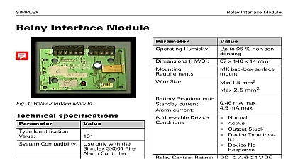
SIMPLEX Input Module Input Module 1 Contact Input Module specifications Identification Compatibility only with the SX501 Fire Controller Application to 70 to 80 to 95 non x 148 x 14 mm g MK backbox mount Temperature Temperature Humidity HWD Requirements current current 1 Technical Specifications Size Wiring Monitored Device 1.5 mm2 2.5 mm2 ohm Normal Active Short Circuit fault Open Circuit fault Device Type Device No 1 Technical Specifications Compatibility Contact Input Module complies with the Product family standard EN 50130 4 in of Conducted Disturbances Radiated Electrostatic Discharge Fast and Slow High Energy EN 61000 6 3 for emissions instructions Doc version 1.0 Input Module Contact Input Module is designed to fire contacts such as extinguishing control ventilation control fire door con etc The Contact Input Module can be config as Two spur circuits Class B monitoring normally open contacts with short giving a fault output Two spur circuits Class B monitoring single closed contacts with short circuit a fault output Single loop circuit Class A monitoring a open contact with short circuit a fault output Single loop circuit Class A monitoring a closed contact with short circuit a fault output Two spur circuits Class B monitoring multi normally open contacts with short circuit an alarm Single loop circuit Class A monitoring normally open contacts with short giving an alarm Contact Input Module monitoring features the following configurable items Identifies all monitored contacts and signals to Fire Controller the status of monitored and wiring to the contacts Can monitor a single normally closed contact Can monitor two Class B spur circuits or a class Class A loop circuit When two Class B spur circuits are con each must be of the same style A contact going to the active state on spur circuit will cause the Contact Input to report the Active State back to the controller An LED reports the Contact Input Module to the user The LED lights when the contact monitored by Contact Input Module has switched to the off normal state The LED when normally off will pulse when Contact Input Module is polled by the notes There are no user circuit settings such as or headers on the Input Module All wiring must conform to the edition of IEE Wiring and BS5839 part 1 All conductors to be free of Fit the PCB to the M520 cover Connect wiring to the monitored For Contact Input Mod typical wiring configurations Figures 6 to 11 Verify the correct polarity of wir before connecting the Input Module to the loop to M520 double cover L L L A B B 2 Contact Input Module fitted onto cover instructions Doc version 1.0 Input Module to install the Contact Input Module an M520 double gang cover Assemble the Contact Input Module onto M520 Double Gang cover using the four and washers provided Snap on the ancillary housing PCB cover Fit the cover onto the MK backbox an IP22 rating is required additional seal must be applied Apply Loctite S1595 sealant around the LED as shown Fig 3 Note how the sealant fills the gap between the LED and its hole in cover Avoid smearing sealant over the surface Using a fine nozzle is recom 3 Sealed LED Cover LED Sealant 4 Contact Input Module Facia Plate Address setting port are to be selected in accordance with 17A 02 D and the requirements of current issue of BS5839 Two pairs of con terminals L and L are provided on the block These terminals are used for con the module onto the addressable circuit maximum of one 1.5mm2 or one 2.5mm2 may be connected at any one terminal equipment module fits onto a standard dual gang MK settings Contact Input Module has a default factory address of 255 this must be set to the loop of the device using an 801AP MX Tool or an 850EMT Program the Contact Module with an address prior to installation the internal programming port 2 or after by using the programming port on front cover see Fig 2 If only one circuit is used the user must be terminated with ohm resistors in parallel a single 68 ohm EOL resistor Use SX Console to configure C normally closed Mode 3 the address has been take note of the device and address number to on site drawings instructions Doc version 1.0 Input Module If only one circuit is used the user must be terminated with ohm EOL resistor Use SX Console to configure C normally open Mode 2 L L L A B B 5 Spur Circuits Class B Normally Closed Circuit A to A or B to B Fault Fire Controller To next device Programming port instructions Doc version 1.0 Input Module L L L A B B L L L A B B 6 Spur Circuits Class B Normally Open Circuit A to A or B to B Fault Fire Controller To next device Programming port Use SX Console to configure E normally closed Mode 6 7 Loop Circuit Class A Normally Closed Circuit A to A or B to B Fault Fire Controller To next device Programming port Use SX Console to configure E normally open Mode 5 instructions Doc version 1.0 Input Module L L L A B B 8 Loop Circuit Class A Normally Open Contact Circuit A to A or B to B Fault Use SX Console to configure B normally open Mode 1 If only one circuit is used the circuit must terminated A 200 ohm EOL resistor L L L A B B 9 Spur Circuit Class B Normally Open Con Circuit between A and A or B and B Fire Controller To next device Programming port instructions Doc version 1.0 Input Module Use SX Console to configure D normally open Mode 4 information Input Module c w 2 Ordering information code L L L A B B 10 Loop Circuit Class A Normally Open Con Circuit between A and A or B and B Fire Controller To next device Programming port instructions Doc version 1.0 Input Module Declaration Performance