Simplex SX501 Relay Interface Module [INTERNATIONAL USE ONLY]
File Preview
Click below to download for free
Click below to download for free
File Data
| Name | simplex-sx501-relay-interface-module-international-use-only-0698427513.pdf |
|---|---|
| Type | |
| Size | 720.36 KB |
| Downloads |
Text Preview
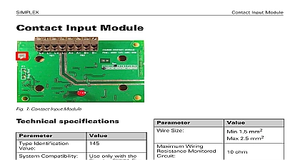
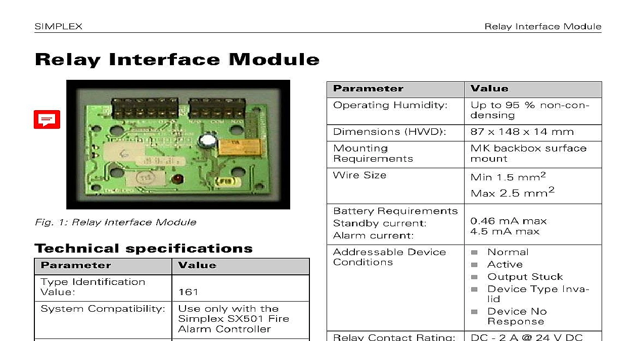
SIMPLEX Interface Module Interface Module Humidity HWD Size Requirements current current Device to 95 non con x 148 x 14 mm backbox surface 1.5 mm2 2.5 mm2 mA max mA max Normal Active Output Stuck Device Type Inva Device No Contact Rating DC 2 A 24 V DC 1 Technical Specifications unit must not be used to switch voltages 1 Relay Interface Module specifications Identification Compatibility Use only with the SX501 Fire Controller Application Temperature to 70 to 80 1 Technical Specifications instructions Doc version 1.0 Interface Module Compatibility Relay Interface Module complies with following Product family standard EN50130 4 in of Conducted Disturbances Immunity Electrostatic Dis Fast Transients and Slow High EN61000 6 3 for emissions Relay Interface Module provides one volt relay changeover contact on a latching relay relay is controlled by a command sent from fire controller via the addressable loop The state activated deactivated or stuck is to the controller Interface Module features include the Addressable functionality control panel sends a command to oper the relay then reports an activated or state back to the fire alarm con panel through the use of a set of contacts to monitor the state of the relay One volt free dry contact relay output LED status indicator which is normally off the Relay Interface Module receives a to activate the LED lights following notes apply There are no user required settings headers on the Relay Interface All wiring must be free of earths All wiring must conform to current edition of Wiring Regulations and BS5839 part 1 See Fig 3 for a simplified diagram of the Interface Module For powered circuit operation route the posi conductor through the Relay Interface to the external device while connect the common neutral conductor to the circuit For dry contact switching connect the exter circuit to the COM and N O or N C termi for normally open or normally closed as required Verify that relay wiring is correct for the Relay Module before connecting to the loop circuit 2 Relay Interface Module Facia Plate Address setting port LED instructions Doc version 1.0 Interface Module programming Relay Interface Module has a default factory address of 255 this must be set to the loop of the device using an 801AP MX Tool or an 850EMT Program the prior to installation using the internal port see Fig 3 on page 3 or after using the programming port on the cover see Fig 2 on page 2 location and address the address has been take note of the device and address number to on site drawings module will accept one 1.5mm2 or one cables information Interface Module cover 2 Ordering information code onto M520 double gang L L L 0 0 N O C N C 3 Relay Interface Module fitted onto M520 Address programming port to install to a M520 double gang Assemble the Relay Interface Module onto M520 Double Gang cover using the four and washers provided Snap on the ancillary housing PCB cover Fit cover onto MK backbox If an IP22 rating is required additional sealing be applied Apply Loctite S1595 silicone around the LED as shown in Fig 4 how the sealant fills the small gap the LED and its hole in the cover smearing sealant over the LED surface a fine nozzle is recommended 4 Sealed LED Cover LED Sealant instructions Doc version 1.0 Interface Module of Performance doc version 1.0 9 April 2018 2018 Johnson Controls All rights reserved All specifications and other shown were current as of document revision date and are subject change without notice Fire Security GmbH Victor von Bruns Strasse 21 8212 Neuhausen Rheinfall Switzerland