Simplex System Accessories, LED Annunciators; 4602 Series SCU (Status Command Units) and RCU (Remote Command Units)

File Preview
Click below to download for free
Click below to download for free
File Data
| Name | simplex-system-accessories-led-annunciators-4602-series-scu-status-command-units-and-rcu-remote-command-units-3058291746.pdf |
|---|---|
| Type | |
| Size | 935.37 KB |
| Downloads |
Text Preview
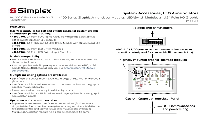
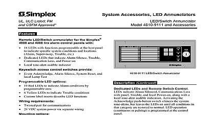
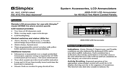
ULC CSFM Listed NYC Acceptance Accessories LED Annunciators 4602 Series SCU Status Command Units RCU Remote Command Units LED status annunciation with available panel input switch control Compatible with Simplex 4005 4007ES 4010ES and 4100U series fire alarm control panels Also compatible with Simplex legacy panel model series 4020 4100 4120 and Universal Transponders UT Supervised RUI remote unit interface communications a single twisted shielded wire pair to the fire control panel power is supplied via a second wire Red zone status LEDs are provided with preprinted zone or can be individually labeled as desired LEDs are pluggable for color changing or replacement internal pushbutton switch provides LED test Surface or flush mount on standard electrical boxes UL listed to Standard 864 as single units or can be ordered for up to 4 units in a common cabinet 4602 9101 Status Command Unit SCU provides red LED zone status indicators 4602 9102 Remote Command Unit RCU provides red LED zone status indicators local power green trouble yellow LEDs local tone alert and for Trouble Silence Alarm Silence System and Manual Evacuation EVAC 4602 8001 Series panels provide selection of a remote that can mount one RCU and up to three SCUs include beige or stainless steel flush mount doors Graphic I O Board Assemblies are available separately use with listed custom graphic annunciator panels stand alone 4602 9150 or plate mounted selectable as SCU or RCU terminal blocks provided for LED switch and LED test feature Command Units SCU provide 16 red zone LEDs Multiples may be mounted together for zone coverage Command Units RCU provide 8 red zone LEDs and control switches duplicating the switch of the host Fire Alarm Control Panel A enables the control switches A green LED power is present and a yellow LED indicates identification i e Zone 1 Zone 2 is provided labels Detailed local zone information may typed on the blank reverse side i e East Wing First etc of the label Pushbutton LED test switches are internally for test feature Terminations via convenient terminal block connections Status Command Unit SCU Remote Command Unit RCU Annunciator Package with RCU on top and SCUs shown as standard surface mount trim This product has been approved by the California State Fire Marshal CSFM pursuant to 13144.1 of the California Health and Safety Code See CSFM Listing for allowable values and or conditions concerning material presented in document It is subject to re examination revision and possible cancellation Accepted use City of New York Department of Buildings MEA35 93E Additional listings may applicable contact your local Simplex product supplier for the latest status Listings and under Simplex Time Recorder Co are the property of Tyco Fire Protection 1 2018 Product Selection LED Switch Annunciators Six Gang box mounting refer to mounting reference on page 3 Reference Status Command Unit SCU with beige trim plate Remote Command Unit RCU with beige trim plate Brushed stainless steel trim plate option for either 4602 9101 or includes both slotted and tamper resistant screws Surface mount box option for use with 4602 9101 or 4602 9102 painted steel ivory finish 11 31 W x 4 H x 2 D 304 mm x 117 mm x 70 mm dimensions 11 13 W x H 114 mm x 300 mm on 6 gang box 1 depth 38 mm Graphic I O Module for use with listed custom graphic annunciator panels Graphic I O RCU SCU Board Assembly operation is switch selectable as either RCU or SCU 5 x 7 130 mm x 178 mm see illustration reference below Mounted Graphic I O Modules for use with listed custom graphic annunciator panels 16 W x 11 H 409 mm x 282 mm Graphic I O Mounting Plate for up to four 4 4602 7101 Graphic I O RCU SCU modules Select when adding 4602 7101 modules in the field to an existing Graphic I O annunciator mounting plate Graphic I O RCU SCU module for mounting on 4602 8103 plate up to four operation is switch selectable as RCU or SCU includes power and control wiring harnesses LED Switch Annunciators Cabinet Mounted see mounting reference on page 4 for dimensions modules ordered separately as listed below Basic annunciator panel includes 2975 9197 beige box and beige surface mount door has space for up to 4 Select when adding features in the field to an existing 4602 Modular LED Switch annunciator cabinet Remote Command Unit RCU module typically one used per 4602 8001 Up to four modules may be for one 4602 8001 Status Command Unit SCU module up to 4 may be selected Select when no 4602 7001 or 4602 6001 modules are to be selected blank filler plates will be provided Beige Stainless Steel Options mount door and trim option overall dimensions 16 W x 20 H 406 mm x 508 mm Eight 8 pluggable Yellow LEDs for field replacement of standard red LEDs Zone labels numbered 1 through 64 4602 9150 Graphic I O RCU SCU Board Only Installation Reference Board size is 5 x 7 130 mm x 178 mm Orientation may be vertical or horizontal Mount within the listed custom graphic annunciator or within a listed steel box close nippled the annunciator Required mounting hardware not supplied 6 32 screws 12.7 mm minimum length 6 9.5 mm minimum length Refer to illustration for details NOTE For multiple custom annunciator Graphic applications use model 4602 7101 for up to four on plate 4602 8103 1 2018 Specifications to 32 VDC from fire alarm control panel SCU Supervisory 36 mA Alarm 55 mA RCU Supervisory 40 mA Alarm 80 mA or I O Module 40 mA Alarm 65 mA minimum up to 2.5 A maximum driver outputs are rated 150 mA maximum each Capacity Per Output Capacity Capacity RUI Capacity Remote Unit Interface external annunciator communications line SLC signaling line circuit to 31 remote annunciators MINIPLEX transponders per channel including the 4603 9101 LCD the SCU and the RCU refer to data sheet S4100 0031 for additional 4100ES to 20 internal or external card addresses including 4603 9101 LCD Annunciators the SCU and RCU refer to data sheets S4010 0004 for additional 4010ES information refer to data sheet for International 4010ES applications to 10 total RUI annunciators to 16 total SCUs and or RCUs refer to data sheet S4005 0001 for additional 4005 information Single twisted shielded pair 18 AWG 0.82 mm2 18 to 12 AWG 0.82 mm2 to 3.31 mm2 A dedicated earth ground connection to the electrical box is required for proper ESD and EMI wire in accordance with NFPA 70 National Electrical Code Article 250 F to 120 F 0 C to 49 C to 93 RH non condensing 90 F 32 C maximum connections are via terminal blocks Temperature Humidity Reference SCU and RCU or 4602 9150 I O Module RCU SCU Mounting Reference Wiring Diagram 841 780 Instructions 574 015 Instructions 574 024 Mount Ganged or Boxes 6 gang box 2 1 2 mm min depth Mount Box model 2975 9206 separately plate 1 5 2 6 3 7 4 8 or RCU 1 2018 4602 8001 Mounting Refer