Simplex TrueAlert Notification Appliances, Non-Addressable Audible Visible Notification Appliances for 4-Wire Operation (Horn Strobe)

File Preview
Click below to download for free
Click below to download for free
File Data
| Name | simplex-truealert-notification-appliances-non-addressable-audible-visible-notification-appliances-for-4-wire-operation-horn-strobe-8275463091.pdf |
|---|---|
| Type | |
| Size | 800.79 KB |
| Downloads |
Text Preview
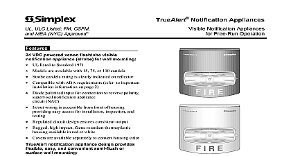
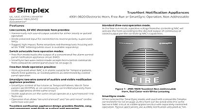
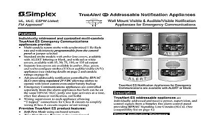
CSFM Listed FM and NYC Approved Notification Appliances Audible Visible Notification for 4 Wire Operation Horn Strobe mount audible visible notification appliances efficient piezoelectric horn and high output strobe for 4 wire control applications strobe visible notification appliance 24 VDC operation with switch selection for free run or flash rate Models available with 15 75 or 110 candela UL listed to Standard 1971 Compatible with ADA requirements refer to important information on page 4 Strobe candela rating is clearly indicated on reflector horn audible notification appliance Low current operation 25 mA 24 VDC Harmonically rich output sound suitable for either or steady operation UL listed to Standard 464 housing colors Red cover with white FIRE lettering White cover with red FIRE lettering easy and convenient semi flush or wall mounting Easily mounts to single gang double gang or 4 inch outlet box Optional mounting adapters are available to cover mounted electrical boxes and to adapt to 2975 9145 boxes Diode polarized inputs for connection to reverse supervised notification appliance circuit NAC wiring terminals for 18 AWG to 12 AWG from front of housing providing easy access installation inspection and testing Rear of housing assembly does not extend into box Rugged high impact flame retardant thermoplastic with optional covers available to convert color Optional UL listed red wire guard is available for semi or surface mounting This product has been approved by the California State Fire Marshal CSFM pursuant to 13144.1 of the California Health and Safety Code See CSFM Listing for allowable values and or conditions concerning material presented in this Accepted for use City of New York Department of Buildings MEA35 93E product was not ULC listed as of document revision date Additional listings may be contact your local Simplex product supplier for the latest status Listings and under Simplex Time Recorder Co are the property of Tyco Fire Protection Non Addressable A V Notification Appliances available in Red with White Lettering and White with Lettering non addressable audible and visible For applications requiring audible visible notification with horn tones these Simplex 4903 appliances combine a high intensity strobe with a current electronic horn in a compact package that is and quick to install Each appliance can be controlled from each other using conventional reverse NACs models with flexible mounting choices 4 wire operation A V appliances are available with strobe intensity levels 15 75 or 110 cd and with or off white housings Mounting can be semi flush or mount on a standard single or double gang or 4 102 mm electrical box Optional accessories are to increase mounting and application flexibility Selection selection of visible notification is dependent on location local codes and proper applications the National Fire Alarm Code NFPA 72 ANSI the appropriate model building code BOCA or SBCCI and the application guidelines of the with Disabilities Act ADA 11 2014 Horn Operation non addressable A V horns provide an notification output that is a loud and penetrating rich sound capable of a continuous or coded per the controlling NAC capabilities Strobe Operation non addressable A V strobes can be set free run operation or synchronized operation using an selection switch When selected for operation flash operation is controlled Synchronized Flash Modules 4905 9914 Class B 4905 9922 Class A 4007ES Hybrid 4008 4010 4010ES 4100ES 4100U Fire Alarm Control Panels refer to product data sheets for details IDNet NAC Extender models 4009 9201 and refer to data sheet S4009 0002 Product Selection Notification Appliances Horn Strobe Notification Appliance Output cd cd cd Color with white lettering with red lettering Surface mount red adapter skirt to cover 1 1 2 surface Surface mount white adapter skirt boxes Red adapter plate for mounting to Simplex 2975 9145 box for retrofit may be mounted vertical or horizontal Red mounting box requires 4905 9931 adapter plate Flash Control Modules Synchronized Flash Module Synchronized Flash Module B operation A operation Covers and Guard encapsulated with 18 AWG wire rated for 2 A NAC 10 mA for power Red cover with white lettering White cover with red lettering Wire guard with mounting plate red compatible with surface semi flush mounted boxes UL listed by Space Age Electronics Inc H x 5 1 4 W x 1 5 8 D mm x 133 mm x 41 mm depth with strobe 4 3 8 111 mm x 5 3 4 x 0.060 Thick mm x 146 mm x 1.5 mm x 5 1 8 x 2 3 4 Deep mm x 200 mm x 70 mm W x 2 7 16 L x 13 16 H mm x 62 mm x 20 mm H x 5 W x 1 1 2 D mm x 127 mm x 38 mm H x 6 1 16 W x 3 1 8 D mm x 154 mm x 79 mm 11 2014 Specifications Specifications Dimensions including lens Range Range Specifications H x 5 W x 2 3 4 D 130 mm x 127 mm x 70 mm to 122 F 0 to 50 C to 93 non condensing at 100 F 38 C blocks for 18 AWG to 12 AWG 0.82 mm2 to 3.31 mm2 two per terminal for in out wiring Voltage Range Rate and Synchronized NAC Loading RMS Current Rating per Strobe Output Note 2 below Listed Range Regulated 24 VDC see Note 1 below Hz with up to 35 synchronized strobes maximum per NAC cd mA mA mA VDC VDC cd mA mA mA cd mA mA mA Currents other voltages Specifications Voltage Range Output Characteristics Output and Ratings 10 ft 3 m Listed Range 16 VDC to 33 VDC see Notes 3 and 4 below to 3700 Hz sweep modulated at 120 Hz rate Type see Note 5 Chamber 464 Test Chamber VDC VDC VDC mA mA mA mA mA mA dBA dBA dBA dBA dBA dBA dBA dBA dBA dBA dBA dBA 24 VDC refers to the voltage range of 16 to 33 VDC per UL Standard 1971 Signaling Devices for the Impaired This voltage range is the absolute operating range Operation outside of this range may cause damage to the appliance Please note that 16 VDC is the lowest operating voltage that is allowed at the last on the NAC under worst case conditions The strobe of this A V is field selectable for free run or synchronized The maximum RMS current listed is the device nameplate rating Strobe designs are constant wattage and the maximum current rating occurs at the lowest allowable operating voltage RMS is root mean square and refers to the value of a varying current waveform Terminals are provided for wiring the horn and strobe of these A Vs to separate NACs Operation of the horn and strobe not separately controlled when they are both wired to the same NAC The rated voltage range listed is the absolute operating range Operation outside of this range may cause permanent to the appliance Please note that 16 VDC