Simplex What Are The Terminations for Battery Supervision Module

File Preview
Click below to download for free
Click below to download for free
File Data
| Name | simplex-what-are-the-terminations-for-battery-supervision-module-9517862304.pdf |
|---|---|
| Type | |
| Size | 571.54 KB |
| Downloads |
Text Preview
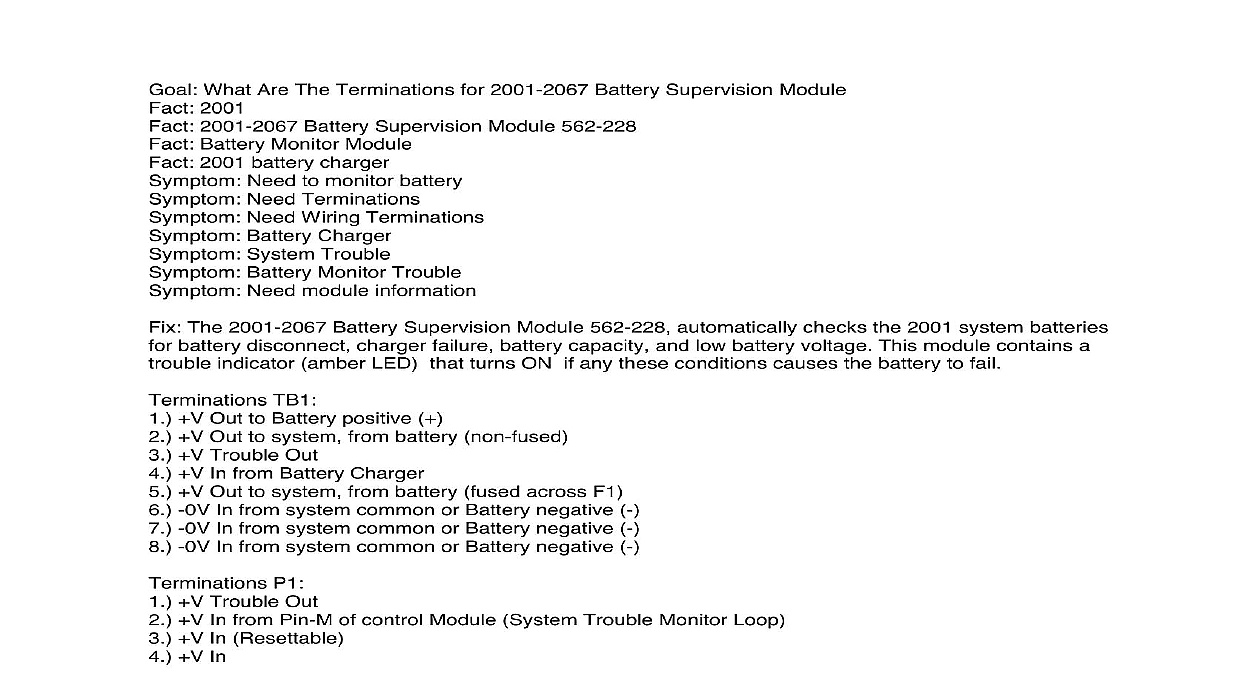
What Are The Terminations for 2001 2067 Battery Supervision Module 2001 2001 2067 Battery Supervision Module 562 228 Battery Monitor Module 2001 battery charger Need to monitor battery Need Terminations Need Wiring Terminations Battery Charger System Trouble Battery Monitor Trouble Need module information The 2001 2067 Battery Supervision Module 562 228 automatically checks the 2001 system batteries battery disconnect charger failure battery capacity and low battery voltage This module contains a indicator amber LED that turns ON if any these conditions causes the battery to fail TB1 V Out to Battery positive V Out to system from battery non fused V Trouble Out V In from Battery Charger V Out to system from battery fused across F1 0V In from system common or Battery negative 0V In from system common or Battery negative 0V In from system common or Battery negative P1 V Trouble Out V In from Pin M of control Module System Trouble Monitor Loop V In Resettable V In Operations Normal condition V In from the battery charger is applied to the Battery Supervisory Module TB1 4 voltage is controlled by a timer circuit that charges the battery through TB1 1 for 90 seconds At the of 90 seconds the timer removes the charger voltage from TB1 1 and performs a battery capacity The battery voltage between TB1 1 V and TB1 7 0V must be 22 VDC or higher in order to relay K1 energized and a no battery trouble condition Trouble condition when the battery voltage drops below 22 VDC because of low battery voltage disconnected the load applied across the batter terminals during the battery capacity test the checking for low battery voltage un picks relay K1 This will apply a V on P1 1 and TB1 3 trouble and the Trouble LED will turn on power outage the plus voltage on P1 2 from the power supply trouble loop is removed This the battery capacity check from being performed The battery voltage from TB1 1 V and TB1 V is sent out TB1 2 or TB1 5 for battery power


