Simplex XPS and XNAC – Installation Instructions

File Preview
Click below to download for free
Click below to download for free
File Data
| Name | simplex-xps-and-xnac-installation-instructions-4039128765.pdf |
|---|---|
| Type | |
| Size | 916.25 KB |
| Downloads |
Text Preview
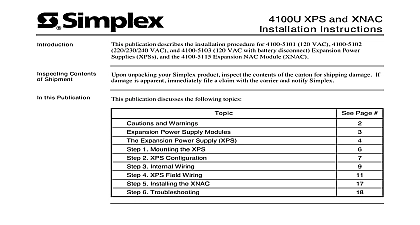
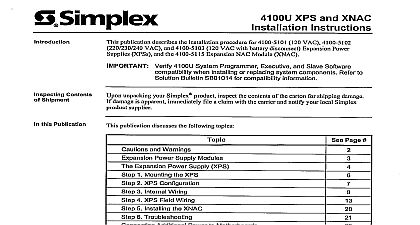
Introduction and XNAC Instructions publication describes the installation procedure for 4100 5101 120 VAC 4100 5102 VAC and 4100 5103 120 VAC with battery disconnect Expansion Power XPSs and the 4100 5115 Expansion NAC Module XNAC product is compatible with 4100U and 4100ES Fire Alarm Control Panels FACP Verify FACP System Programmer Executive and Slave Software when installing or replacing system components Refer the Technical Support Information and Downloads website for information this Publication publication discusses the following topics and Warnings Power Supply Modules Expansion Power Supply XPS 1 Mounting the XPS 2 XPS Configuration 3 Internal Wiring 4 XPS Field Wiring 5 Installing the XNAC 6 Troubleshooting Additional Power to Motherboards 5 6 2005 2011 SimplexGrinnell LP All rights reserved and other information shown were current as of publication and are subject to change without notice and the Simplex logo are trademarks of Tyco International Ltd and its affiliates and are used under license K and Warnings AND SAVE THESE INSTRUCTIONS Follow the instructions in this installation These instructions must be followed to avoid damage to this product and associated Product operation and reliability depend upon proper installation NOT INSTALL ANY SIMPLEX PRODUCT THAT APPEARS DAMAGED Upon your Simplex product inspect the contents of the carton for shipping damage If is apparent immediately file a claim with the carrier and notify an authorized product supplier HAZARD Disconnect electrical field power when making any internal adjust or repairs All repairs should be performed by a representative or authorized agent of local Simplex product supplier HAZARD Static electricity can damage components Handle as follows yourself before opening or installing components to installation keep components wrapped in anti static material at all times RULES AND REGULATIONS PART 15 This equipment has been tested and to comply with the limits for a Class A digital device pursuant to Part 15 of the FCC These limits are designed to provide reasonable protection against harmful when the equipment is operated in a commercial environment This equipment uses and can radiate radio frequency energy and if not installed and used in with the instruction manual may cause harmful interference to radio Operation of this equipment in a residential area is likely to cause harmful in which case the user will be required to correct the interference at his own REACCEPTANCE TEST AFTER SOFTWARE CHANGES To ensure system operation this product must be tested in accordance with NFPA72 1996 7 after any programming operation or change in site specific software testing is required after any change addition or deletion of system components after any modification repair or adjustment to system hardware or wiring components circuits system operations or software functions known to be affected by a must be 100 tested In addition to ensure that other operations are not affected at least 10 of initiating devices that are not directly affected by the up to a maximum of 50 devices must also be tested and proper system operation and Power Supply Modules publication describes the installation procedure for the following Expansion Power Supply XPS 120 VAC 60 Hz XPS 220 230 240 VAC 50 60 Hz XPS 120 VAC 60 Hz with battery disconnect Canada Expansion NAC Module XNAC XPS distributes added card power and signal power via the PDI Signal power is available only in bay in which the XPS is located The source of card power is selected by jumpers P4 P5 on the XPS includes 3 NACs and may be expanded to 6 NACs with the 4100 5115 NACs are wired as B or Class A All circuits are power limited per UL 864 The NACs support TrueAlert and conventional reverse polarity operation Notification Appliance Circuits on these modules can be used as regulated 24 DC circuits or application circuits When used as generic 24 VDC regulated circuits only 4 Amps of current available across the 3 circuits and any 24 VDC appliance may be attached When used as special NACs the full 9 Amps of current is available at the 3 circuits and only the compatible listed on page 27 may be connect to these circuits The SPS RPS can synchronize appliances across all 3 circuits when those circuits are used as special applications NACs XPS has a 9 A capacity Each NAC is rated at 3 A A NAC can also be configured as an auxiliary point in which case it is rated at 2 A The total load at 24 VDC must be no more than 9 A The load includes NACs on the XPS or the XNAC Module auxiliary power card power and signal used by modules plugged into the same bay NACs are to be used as auxiliary outputs they must be configured as such in the Programmer Programming may also be required for dedicated auxiliary refer to the ES Panel Programmer Manual 574 849 are monitored for short and open circuits If a short circuit occurs the affected NAC will not be NAC miswiring test which checks for NACs that are shorted together can be initiated on command the operator interface power and battery backup are provided to the XPS through a connection to the PDM of an earth fault on XPS wiring is performed by the SPS RPS or XBC Detection is 10k minimum model 4100 5103 are required in jurisdictions such as Canada where depleted battery conditions required by local code to result in power down of the unit until AC power is restored The system also be programmed for depleted battery cutout for each power supply Expansion Power Supply XPS Features 1 below is an illustration of the XPS COMMS TO PDI P2 STATUS LED CONNECTOR side TERMINAL TB1 A LED INPUT TROUBLE LED6 POWER P1 DIP SW1 STATUS A NAC A AUX A NAC A AUX A NAC A AUX 1 The Expansion Power Supply Expansion Power Supply XPS Continued XPS has the following LEDs yellow Illuminates when NAC 1 is active or in a trouble state otherwise it is off yellow Illuminates when NAC 2 is active or in a trouble state otherwise it is off yellow Illuminates when NAC 3 is active or in a trouble state otherwise it is off green Illuminates when the XPS is running off of AC power otherwise it is off yellow General Status LED On steady Overcurrent tripped Single repeating flash Battery not connected yellow Illuminates when communication loss with the CPU occurs Normally off initialization of the XPS LEDs 1 2 3 illuminate because the NACs are held in the stage and create an open circuit trouble and Output 1 summarizes the input and output specifications for the XPS 1 Input and Output Specifications Input Specifications Output Specifications XPSs VAC 60 Hz nominal 4 A Max VAC 50 or 60 Hz A Max 19.5 VDC 32 VDC 2 VDC p p full load 9 A Range 4100U 4100ES modules are rated to operate at ambient temperatures from 32oF 120oF 0oC 49oC The 4100U 4100ES modules are rated for operation at 90oF 32oC 93 RH non condensing 1 Mounting the XPS XPS is normally mounted on the rightmost top and bottom positions of the PDI in a 4100 cabinet Before mounting the XPS follow these guidelines Disconnect power to the system or remove power at the breaker before mounting or any modules Use Figure 2 and the fo