Solidyne sLON-5x, 6x Data Sheet

File Preview
Click below to download for free
Click below to download for free
File Data
| Name | solidyne-slon-5x-6x-data-sheet-4612053798.pdf |
|---|---|
| Type | |
| Size | 934.09 KB |
| Downloads |
Text Preview
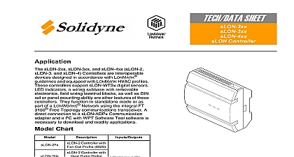
TECH DATA SHEET VAV Controller a n d la cla B re to le e d R s le m bro d C Cla B digital a m all re of th C Interfere E R th m c u o m n c h interfere a 2 T d m a a interfere re in d c with P 1 of th F R O is s to th follo tw c 1 T A E in a 5 M Cla 2 1 M Cla 2 2 3 M C f 0.4 2 0.4 M Total L Te 4 to D lo 2 5 Cla 2 0 0 a n d la cla B re to le e d R E R Cla B digital a m all re of th C Interfere c u o T d m a a interfere re in interfere th tw c 1 T d m n c h interfere a d c with P 1 of th F R O is s to th A E P B S S C 2 CIR O E S O FIR D N E in a 0 0 2 0.4 3 M 5 M Cla 2 1 M Cla 2 2 0.4 M Total L Te 4 to D lo 2 5 Cla 2 sLON 5 and sLON 6 Controllers are interoperable designed in accordance with LONMARK When programmed using WPT Software these controllers provide control for fan coil and ventilator applications These controllers feature terminal blocks three universal inputs to respond to one of five input one sLON 5 or three sLON 6 high voltage output s four 24 Vac Triac digital outputs and S Link interface for connection to an optional digital sensor sLON 5 and sLON 6 controllers conform to the Fan Coil Unit functional profile 8020 open communication and interoperability with party LONMARK devices and greater freedom in design These controllers can function in mode or as part of a LONWORKS TP FT 10 Topology network Chart Outputs Coil Controller One High Relay Coil Controller Three High Relays 3 Universal Inputs 4 DO Triacs capable of a total load of A 24 Vac 1 DO Relay Output Vac 3 A S Link Support 3 Universal Inputs 4 DO Triacs capable of a total load of A 24 Vac 3 DO Relay Outputs Vac 3 A S Link Support carton for damage If notify carrier Inspect for damage upon Corporation www solidyne com sLON 6 rev1 03 2005 must be an experienced technician Tools Drill and bits Digital Volt ohm meter DVM Static protection wrist strap Class 2 power transformer supplying a nominal 24 Vac 20.4 to 30 Vac 50 60 Hz For specifications see the Supply Wiring section on page 14 Suitable grounded metal enclosure to prevent the possibility of accidental contact with high voltage terminals Four 6 self starting screws or 35 mm DIN rail for mounting Terminators if a LONWORKS network is used One sLON T1 terminator required for each free topology segment Two sLON T2 terminators required for each bus topology segment Accessories as required sLON WTSx S Link Sensors 470k ohm 1 4 watt resistor if shielded wire is used for S Link wiring Approved Category 4 or 5 twisted pair two conductors cable optional LONWORKS 0.205 mm2 24 AWG or larger twisted pair voice grade telephone wire for UI connection and DI wiring 10K ohm Thermistor Sensor with 11K ohm Shunt Resistor Platinum Sensor Balco Sensor 1K Balco or platinum element resistive sensor 0 to 5 Vdc analog voltage transmitter 4 to 20 mAdc analog current transmitter Digital dry switched contact switched contact resistance must be less than ohms for closed contact and greater than 1.5K ohms for open contact sLON 6 rev1 03 2005 The sLON 5 and sLON 6 controllers are not suitable for exposed mounting a wall or panel or in any other easily accessible place due to the possibility of contact with the high voltage terminals They must be mounted inside a grounded metal enclosure Figure 2 Electrical shock hazard Disconnect power from the controller and any digital before installing or removing the cover Follow Static Precautions when installing this equipment Use copper conductors that are suitable for 75 167 Make all connections according to electrical wiring diagram national and local electrical Precautions charges damage electronic components The microprocessor and associated circuitry extremely sensitive to static discharge Use the following precautions when installing or operating the system Work in a static free area Discharge static electricity by touching a known securely grounded object Use a wrist strap connected to earth ground when handling the controller printed board Communications Commission FCC equipment has been tested and found to comply with the limits for a Class B digital pursuant to Part 15 of the FCC Rules These limits are designed to provide protection against harmful interference in residential installations This generates uses and can radiate radio frequency energy and may cause harmful if not installed and used in accordance with the instructions Even when are followed there is no guarantee that interference will not occur in a particular If this equipment causes harmful interference to radio or television reception ca