Solidyne sLON-7x Data Sheet

File Preview
Click below to download for free
Click below to download for free
File Data
| Name | solidyne-slon-7x-data-sheet-9032578641.pdf |
|---|---|
| Type | |
| Size | 806.05 KB |
| Downloads |
Text Preview
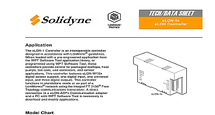
TECH DATA SHEET Controller Enclosure 1 1 1 2 2 2 3 3 3 4 4 4 5 5 5 6 6 6 7 7 7 8 8 8 H G Card Enclosure sLON 7 Controllers are programmable LONWORKS based control devices sLON 7 Series Controller features eight universal four analog outputs eight digital outputs a volt reference LED indication and support for sensors Additionally network capability provided through the use of a FTT 10 transceiver the controller to communicate to other devices part of a LONWORKS Free Topology network A direct connection to a Communication adapter and a PC with Software Tool is necessary to download and applications applications include central station air VAV air handlers fan coil units unit and cooling towers Chart Wall Mount Enclosure Enclosure Card with Backed up Time items not provided carton for damage If notify carrier Inspect for damage damaged products must be a experienced Job wiring diagrams Tools Drill and bits for Corporation www solidyne com rev1 03 2005 mounting screws Digital Volt ohm meter DVM Static protection wrist strap Class 1 or Class 2 power transformer supplying a nominal 24 Vac 20.4 to 30 Vac with minimum rating of 20 VA 50 60 Hz per controller plus Digital Output DO loads if transformer is used In European Community transformer must conform to standards Terminators One sLON T1 terminator required for free topologies Two sLON T2 terminators required for bus topologies Electrical shock hazard Disconnect power before installing or removing the Follow Static precautions when installing this equipment Use copper conductors that are suitable for 167 75 Make all connections according to electrical wiring diagram national and local electrical Precautions charges damage electronic components The microprocessor and associated circuitry extremely sensitive to static discharge Use the following precautions when installing or operating the system Work in a static free area Discharge static electricity by touching a known securely grounded object Use a wrist strap connected to earth ground when handling the controller printed board Communications Commission FCC equipment has been tested and found to comply with the limits for a Class B digital pursuant to Part 15 of the FCC Rules These limits are designed to provide protection against harmful interference in residential installations This generates uses and can radiate radio frequency energy and may cause harmful if not installed and used in accordance with the instructions Even when are followed there is no guarantee that interference will not occur in a particular If this equipment causes harmful interference to radio or television reception can be determined by turning the equipment off and on user is encouraged to to correct the interference by one or more of the following measures Reorient or relocate the receiving antenna Connect the equipment to an outlet on a circuit different from that to which the receiver the separation between the equipment and receiver connected Consult the dealer or an experienced radio television technician for help Department of Communications DOC class B digital apparatus meets all requirements of the Canadian Interference Causing Regulations appareil numerique de la classe B respecte toutes les exigences du Reglement sur le broilleur du Canada Community Directives equipment meets all requirements of European Community Directives for Low Voltage and Electromagnetic Compatibility 89 336 EEC This is a class A product In a domestic environment this product may cause interference in which case the user may be required to take adequate measures rev1 03 2005 controllers are suitable for indoor use only Avoid locations where excessive moisture corrosive fumes vibration or explosive are present Avoid electrical noise interference Do not install near large contactors electrical or welding equipment Locate where ambient temperatures do not exceed 140 60 or fall below 40 and relative humidity does not exceed 95 or fall below 5 non condensing Mount Installation ENC sLON 7 P uses a sheet metal mounting plate The enclosure has four mounting holes in a vertical position as shown in Figure 1 Allow access for wiring and removal of the for service the mounting holes provided Drilling holes in the controller or mounting plate voids warranty Do not drill into mounting plate or any other part of controller Metal chips and other may short circuit electronic components Select mounting location Using four 8 pan head screws mount base of controller to a panel Wire controller See Wiring section After wiring remove aluminum cover plate Remove protective tape from edge of card connector printed circuit board See sLON 7 Printed Circuit Board Installation View 21 19 178 216 View in mm ENC sLON 7 P Panel Mounting Dimensions Mount Installation ENC sLON 7 W rev1 03 2005 use a sheet metal enclosure The enclosure has four mounting holes and combination knockouts 1 2 to 3 4 see Figure 2 Mount in a vertical position and access for wiring and removal of the printed circuit board assembly for service the mounting holes and knockouts provided Drilling holes in the controller or enclosure voids the warranty Do not drill into the enclosure or any other part of the controller Metal chips and other may short circuit electronic components Select mounting location Remove cover Using four 8 pan head screws mount controller Wire controller See Wiring section Remove protective tape from edge of card connector printed circuit board See sLON 7 Printed Circuit Board Installation shown are the cover Overall with the cover 10 7 8 x 8 1 2 x 4 1 4 x 216 x 108 32 187 29 2 Knockouts 22 and 1.125 29 1 2 or 3 4 Conduit View View 32 178 216 View in mm 29 187 2 ENC sLON 7 W Wall Mounting Dimensions Figure 3 for terminal connections power transformer supplying a nominal 24 Vac 20.4 to 30 Vac with a minimum rating of VA 50 60 Hz per controller is required The supply to the transformer must be provided a circuit breaker or disconnect Use class 1 wiring for the transformer wiring 22 19 rev1 03 2005 Wiring must not cid 31 30 Vac RMS Volt Source 20 mA resistive inputs cid 31 to four 1K to 15K ohm cid 31 can be driven by cid 31 source Input or Speed Pulse Input pulse count cid 31 is 10 per second cid 31 50 duty cycle Inputs interface with analog cid 31 digital input devices Outputs 0 to 20 mA outputs cid 31 to interface with cid 31 controlled devices 1 cid 31 2 cid 31 3 cid 31 4 cid 31 5 cid 31 6 cid 31 7 cid 31 8 cid 31 1 cid 31 2 cid 31 3 cid 31 4 cid 31 Voltage Side voltage input wiring Voltage Side wiri