System Sensor 1151 Manual

File Preview
Click below to download for free
Click below to download for free
File Data
| Name | system-sensor-1151-manual-7802651439.pdf |
|---|---|
| Type | |
| Size | 648.79 KB |
| Downloads |
Text Preview
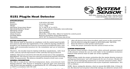
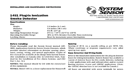
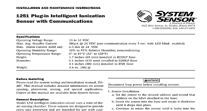
INSTALLATION AND MAINTENANCE INSTRUCTIONS Low Profile Ionization Smoke Detectors 3825 Ohio Avenue St Charles Illinois 60174 FAX 630 377 6495 1.7 inches 43 mm 4.0 inches 102 mm 3.6 oz 102 g Temperature Range to 60 14 to 140 NOTE Do not install in locations where normal ambient temperature range extends beyond 0 to 49 32 to 120 Humidity Range 10 to 93 Relative Humidity Noncondensing Alarm Reset by momentary power interruption Installing thoroughly read the System Sensor manual A05 Applications Guide for System Smoke Detectors provides detailed information on detector spacing zoning wiring and special applications Copies this manual are available from System Sensor Selection and Wiring Guide to the installation instructions for the plug in detector for wiring instructions System Sensor has available a of detector bases for this smoke detector including applications with and without relays and or current resistors 4 wire and 120 VAC applications This manual should be left with the owner user this equipment The detector used with this base must be and maintained regularly following NFPA 72 require The detector used with this base should be cleaned least once a year Description 1151 ionization detector uses state of the art sens chambers This detector is designed to provide open protection and to be used with compatible UL listed panels only The capability of plugging this detector a variety of special bases makes it more versatile than direct wired models LEDs on each detector light to provide a local 360 vis alarm indication Remote LED annunciator capability available as an optional accessory This detector also has latching alarm feature The alarm can be reset only by momentary power interruption For testing this detector an internal magnetically activated reed switch of 30 ft on a smooth ceiling as per NFPA 72 conditions or response requirements vary other may apply bases are provided with screw terminals for power remote annunciator connections and relay contact if applicable The electrical ratings for each combination are also included in the base instructions All wiring must conform to applicable local codes and regulations Verify that all detector bases are installed that the circuits have been tested and that wiring is correct power from initiating device circuits before install detectors Install Detectors a Place the detector into the detector base b Rotate the detector clockwise until the detector drops place c Continue rotating the detector clockwise to lock it in Tamper Resistance The detector bases include a feature when activated prevents removal of the detector the use of a tool See the installation instruc manual of the detector base for details in using this 1 I56 546 08R After all detectors have been installed apply power to control unit Test the detector as described under TESTING Reset the detector at the system control panel Notify the proper authorities that the system is in opera 2 Both LEDs should latch on within 30 seconds indicating an alarm and annunciating the panel Calibrated Sensitivity Test MOD400R Use the MOD400R Test Module with a digital or ana voltmeter to test calibrated detector sensitivity as in the test module manual covers are an effective way to limit the entry of dust smoke detector sensing chambers However they may completely prevent airborne dust particles from enter the detector Therefore System Sensor recommends the of detectors before beginning construction or other producing activity Be sure to remove dust covers from sensors that were left in place during construction as of returning the system to service detectors are not to be used with detector guards the combination has been evaluated and found for that purpose must be tested after installation and following maintenance However before testing notify the authorities that the smoke detector system is under maintenance and the system will be temporarily out service Disable the zone or system undergoing mainte to prevent unwanted alarms addition check to ensure that the LEDs blink If they do power has been lost to the detector check the wiring it is defective return for repair the sensors as follows Test Magnet p n M02 04 01 or M02 09 00 1 Test the sensor by positioning the optional test mag against the sensor plastic just to the left of LED1 1 Aerosol Generator Gemini 501 Set the generator to represent 4 ft to 5 ft obscura as described in the Gemini 501 manual Use the shaped applicator to apply aerosol to the sensor It alarm within 30 seconds the proper authorities that the system is back on Detectors that fail these tests should be cleaned as under MAINTENANCE and retested If the detec still fail these tests they should be returned for repair cleaning notify the proper authorities that the sys is undergoing maintenance and will be temporarily of service Disable the system to prevent unwanted Remove the sensor to be cleaned from the system Remove the sensor cover Use a small standard screw to release each of four cover removal tabs hold the cover in place Vacuum the outside of the screen carefully without it Remove the sensor screen Pull the screen straight away the sensing chamber until it snaps out of place screens are available Use a vacuum cleaner or clean compressed air to remove and debris from the sensing chamber Reinstall or replace the sensing chamber screen by slid the edge without the tabs over the sensing chamber sure that one of the Screen Contacts touches the Board Contact 1 Bottom and side views showing position of test magnet 2 I56 546 08R Reinstall the sensor cover Use the test module socket LEDs to align the cover with the sensor Snap the into place When all sensors have been cleaned restore power to system and test the sensor s as described in the section of this manual 2 Note Regarding Smoke Detector Guards detectors are not to be used with detector guards the combination has been evaluated and found for that purpose 3 I56 546 08R refer to insert for the Limitations of Fire Alarm Systems Limited Warranty Sensor warrants it