System Sensor 1251B Manual

File Preview
Click below to download for free
Click below to download for free
File Data
| Name | system-sensor-1251b-manual-8509463712.pdf |
|---|---|
| Type | |
| Size | 1.25 MB |
| Downloads |
Text Preview
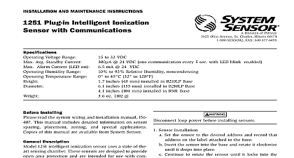
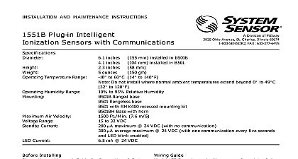
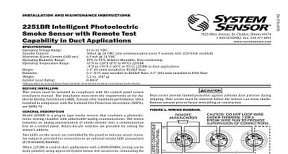
INSTALLATION AND MAINTENANCE INSTRUCTIONS Plug in Intelligent Sensor with Communications 3825 Ohio Avenue St Charles Illinois 60174 FAX 630 377 6495 Voltage Range Average Standby Current Alarm Current LED on Humidity Range Temperature Range to 32 VDC 24 VDC one communication every 5 seconds with LED blink enabled mA 24 VDC to 93 Relative Humidity Non condensing to 120 0 to 49 51 mm installed in B210LP Base 155 mm installed in B210LP Base 4.1 104 mm installed in B501 Base oz 153 g 1 WIRINg DIAgRAM INSTALLINg sensor must be installed in compliance with the control panel system manual The installation must meet the requirements of the Au Having Jurisdiction AHJ Sensors offer maximum performance when in compliance with the National Fire Protection Association NFPA NFPA 72 DESCRIPTION 1251B intelligent ionization sensor uses a state of the art sensing cham These sensors are designed to provide open area protection and are in for use with compatible control panels only LEDs on each sensor light to provide a local visible sensor indication LED annunciator capability is also available as an optional accessory 1251B requires compatible addressable communications to function Connect this sensor to listed compatible control panels only Sensor recommends spacing sensors in compliance with NFPA 72 In air flow applications with smooth ceilings space sensors 30 feet apart specific information regarding sensor spacing placement and special ap refer to NFPA 72 or the System Smoke Detector Application Guide from System Sensor gUIDE wiring must be installed in compliance with the National Electrical Code local codes and any special requirements of the Authority Having Proper wire gauges should be used The installation wires should color coded to limit wiring mistakes and ease system troubleshooting Im connections will prevent a system from responding properly in the of a fire power from the communication line before installing sensors Wire the sensor base supplied separately per the wiring diagram see 1 the desired address on the sensor address switches see Figure 2 Install the sensor into the sensor base Push the sensor into the base turning it clockwise to secure it in place After all sensors have been installed apply power to the control unit and the communication line Test the sensor s as described in the TESTING section of this manual covers provide limited protection against airborne dust particles during Dust covers must be removed before the sensors can sense smoke sensors prior to heavy remodeling or construction DO NOT LOOP WIRE TERMINAL 1 OR 2 WIRE RUN TO PROVIDE OF CONNECTIONS A OPTIONAL WIRING 2 ROTARy DECADE ADDRESS SWITChES 0 0 1251B includes a tamper resistant capability that prevents their re from the bracket without the use of a tool Refer to the base manual for on making use of this capability testing notify the proper authorities that the system is undergoing and will temporarily be out of service Disable the system to unwanted alarms sensors must be tested after installation and periodically thereafter Testing must satisfy the Authority Having Jurisdiction AHJ Sensors offer max performance when tested and maintained in compliance with NFPA 72 the sensors as follows Functional Magnet Test P N M02 04 01 or M02 09 00 This sensor can be functionally tested with a test magnet The test mag electronically simulates smoke in the sensing chamber testing the electronics and connections to the control panel Hold the test magnet in the magnet test area as shown in Figure 3 The sensor should alarm the panel Two LEDs on the sensor are controlled by the panel to indicate sensor Coded signals transmitted from the panel can cause the LEDs blink latch on or latch off Refer to the control panel technical docu for sensor LED status operation and expected delay to alarm Smoke Entry The GEMINI model 501 aerosol generator can be used for smoke entry Set the generator to represent 4 ft to 5 ft obscuration as de in the GEMINI 501 manual Using the bowl shaped applicator aerosol until the panel alarms Additionally canned aerosol simulated smoke canned smoke agent be used for smoke entry testing of the smoke detector Tested and aerosol smoke products are Safeguard Industries used properly the canned smoke agent will cause the smoke detector go into alarm Refer to the manufacturer published instructions for proper of the canned smoke agent aerosol simulated smoke canned smoke agent formulas will vary by Misuse or overuse of these products may have long term ad effects on the smoke detector Consult the canned smoke agent manufac published instructions for any further warnings or caution statements sensor that fails any of these tests should be cleaned as described under and retested If the sensor fails after cleaning it must be replaced testing is complete restore the system to the normal operation and no the proper authorities that the system is back in operation 3 TEST MAgNET POSITIONINg TEST MAGNET cleaning notify the proper authorities that the system is undergoing and will be temporarily out of service Disable the system to unwanted alarms Remove the sensor to be cleaned from the system Remove the sensor cover Press firmly on each of the four removal tabs hold the cover in place Vacuum the outside of the screen carefully If further cleaning is required with Step 4 otherwise skip to Step 5 Use clean compressed air to remove dust and debris from the sensing Replace the cover using the LEDs to align the cover and then gently it until it locks into place Reinstall the detector Test the detector as described in TESTING Reconnect disabled circuits Notify the proper authorities that the system is back on line NOTE REgARDINg SMOkE DETECTOR gUARDS detectors are not to be used with detector guards unless the combina has been evaluated and found suitable for that purpose 4 STATUS TEST MAGNET SCREEN refer to insert for the Limitations of Fire Alarm Systems LIMITED WARRANTy Sensor warrants its enclosed smoke detector to be free from defects in materials workmanship under normal use and service for a period of three years from date manufacture System Sensor makes no other express warranty for this smoke detec No agent representative dealer or employee of the Company has the authority to or alter the obligations or limitations of this Warranty The Company obligation this Warranty shall be limited to the repair or replacement of any part of the smoke which is found to be defective in materials or workmanship under normal use service during the three year period commencing with the date of manufacture phoning System Sensor toll free number 800 SENSOR2 736 7672 for a Return number send defective units postage prepaid to System Sensor Returns RA 3825 Ohio Avenue St Charles IL 60174 Please include a describing the malfunction and suspected cause of failure The Company shall not obligated to repair or replace units which are found to be defective because of damage use modifications or alterations occurring after the date of manufacture no case shall the Company be liable for any consequential or incidental damages for of this or any other Warranty expressed or implied whatsoever even if the loss damage is caused by the Company negligence or fault Some states do not allow the or limitation of incidental or consequential damages so the above limitation exclusion may not apply to you This Warranty gives you specific legal rights and you also have other r