System Sensor 1412 and 1424 Install and Maint Instructions

File Preview
Click below to download for free
Click below to download for free
File Data
| Name | system-sensor-1412-and-1424-install-and-maint-instructions-8214607539.pdf |
|---|---|
| Type | |
| Size | 766.14 KB |
| Downloads |
Text Preview
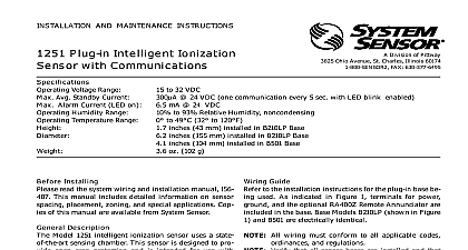
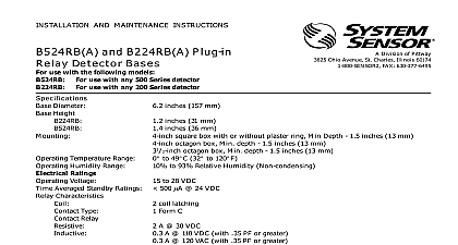
SYsTEM SENSOR Division of Pittway 3825 Ohio Avenue St Charles Illinois 60174 FAX 630 377 6495 AND MAINTENANCE INSTRUCTIONS inches 14 cm inches 8.0 cm lb 310 gm to 49 cid 176 C 32 cid 176 to 120 cid 176 F to 93 Relative Humidity Non condensing by momentary power interruption and 1424 Direct Wire Smoke Detectors Temperature Humidity Alarm Contact Ratings or Inductive 60 power factor load A C 30VAC DC 110VDC 2.0A 30VDC 125VAC 2.0A 30VAC Canadian installations relay contact rating is 2.0A 30VAC DC Ratings Voltage Voltages Voltages Current Currents 4V Maximum Ripple Minimum Maximum Minimum A Maximum Minimum Maximum alarm and auxiliary relay operate within the specified voltage ratings Time Time Installing thoroughly read the System Sensor manual I56 407 Guide for Proper Use of System Smoke Detectors which detailed information on detector spacing place zoning wiring and special applications Copies of manual are available at no charge from System Sensor installation in Canada refer to CAN ULC S524 Stan for the Installation of Fire Alarm Systems and CEC Part Sec 32 Description Sensor 1412 and 1424 dual chamber ionization detectors utilize state of the art unipolar sensing These detectors are designed to provide open protection and to be used with UL listed 4 wire con panels The 1412 for 12 volt panels operates at 12VDC the 1424 for 24 volt panels operates at 24VDC The de operation and sensitivity can be tested in place detectors are listed to UL 268 and are latching type detectors When latched in alarm the detectors be reset by a momentary power interruption LED on the detector provides a local indication of the status If power is applied to the detector and the is functioning properly in standby the status LED blink every 10 seconds In alarm the LED will be on continuously until the detector is reset detector contains one Form A SPST NO contact for to the alarm initiating circuit and one Form C set of auxiliary contacts Supervision of de power is accomplished by installing a Power Supervi End of Line Relay Module A77 716 at the end of the power loop When power is applied to and the detectors the EOL Power Supervisory Module energized Its relay contacts close and provide a closed circuit in the control panel alarm initiating loop A failure or a break in the detector power loop de ener the EOL Module The relay contacts open and trigger trouble signal at the control panel Manuals Online 1 Flush mounting of detector on 4 inch box 2 Detector mounting bracket MAKE DETECTOR TAMPER RESISTANT OFF TAB EXTENSION SCRIBED LINE 1412 and 1424 detector is supplied with a mounting kit that permits the detector to be mounted Directly to a 3 1 2 inch or 4 inch octagonal 1 1 2 inch Refer to releasing device manufacturer installa instruction for proper connections Contacts are shown in stand by mode and will in alarm condition electrical box or To a 4 inch square electrical box by using a plaster ring the supplied mounting bracket kit of 30 ft on a smooth ceiling as per NFPA 72E conditions or response requirements vary other may apply Installation Guidelines wiring must be installed in compliance with the Na Electrical Code and the applicable local codes and special requirements of the local authority having juris Proper wire gauges should be used The conduc used to connect smoke detectors to control panels and devices should be color coded to prevent wiring Improper connections can prevent a system from properly in the event of a fire system supervision for terminals 1 2 7 and 8 do not looped wire under terminals Break wire run to provide supervision of connections signal wiring the wiring between interconnected de it is recommended that the wire be no smaller 18 gauge Wire sizes up to 12 gauge wire may be used best system performance the power and loop should be twisted pair and installed in separate conduit to protect the loop from extraneous elec interference detectors and alarm system control panels have for allowable loop resistance Consult the panel manufacturer specifications for the total resistance allowed for the particular model control being used before wiring the detector loops 3 Wiring diagram for models 1412 and 1424 detectors used with Class A or B four wire control panels 1 C A LISTED 1 8 5 1 8 5 A OPTIONAL WIRING Manuals Online connections are made by stripping about 3 8 of insu from the end of the wire use strip gauge molded in sliding the bare end of the wire under the clamping and tightening the clamping plate screw A typical diagram for a 4 wire detector system is shown in 3 Before testing notify the proper authorities that smoke detector system is undergoing mainte and therefore will temporarily be out of ser Disable the zone or system undergoing to prevent unwanted alarms Feature detector includes a tamper proof feature that when prevents removal of the detector without the use a tool To activate this feature break off the smaller tab the scribed line on the tamper proof tab located on the mounting bracket see Figure 2 then install the To remove the detector from the bracket once the feature has been activated depress the tab located in the slot on the mounting see Figure 4 and turn the detector counterclock for removal power from initiating device circuits before install detectors Wire detector per installation guidelines Line up arrows on the detector with arrows on the Turn the detector clockwise until it clicks into place After all detectors have been installed apply power to bracket control unit Test the detector as described under TESTING Reset the detector at the system control panel Notify the proper authorities the system is in operation covers can be used to help limit dust entry to the de but they are not a substitute for removing the detec during building construction Remove any dust covers placing system in service testing the detector look for the presence of the LED If it does not flash power has been lost to the check the wiring or it is defective return for re see warranty information must be tested after installation and following maintenance The 1412 and 1424 may be tested as Recessed Test Switch A test switch is located on the detector housing see Push and hold the recessed test switch with a 0.1 inch diameter tool The LED on the detector should light within 30 4 Reset the detector at the system control panel Test Module System Sensor Model No MOD400R MOD400 or MOD400R is used with an analog or voltmeter to check the detector sensitivity as de in the test module manual Aerosol Generator Gemini 501 the generator to represent 4 ft to 5 ft obscura as described in the Gemini 501 manual Using the shaped applicator apply aerosol until unit alarms the proper authorities the system is back on line that fail these tests should be cleaned as de under MAINTENANCE and retested If the detec