System Sensor 1551B Manual

File Preview
Click below to download for free
Click below to download for free
File Data
| Name | system-sensor-1551b-manual-2153897064.pdf |
|---|---|
| Type | |
| Size | 617.46 KB |
| Downloads |
Text Preview
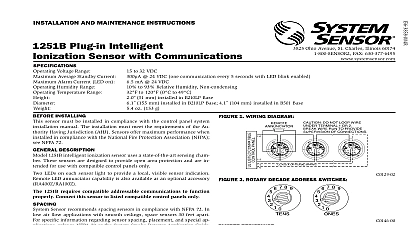
INSTALLATION AND MAINTENANCE INSTRUCTIONS Plug in Intelligent Sensors with Communications Division of Pittway 3825 Ohio Avenue St Charles Illinois 60174 FAX 630 377 6495 Temperature Range Humidity Range Air Velocity Range Current Current mm installed in B501B mm installed in B501 mm gm inches inches inches ounces to 60 C 14 to 140 F Do not install where normal ambient temperatures extend beyond 0 to 49 C to 120 F to 93 Relative Humidity flanged base flangeless base with RMK400 recessed mounting kit Base with horn Ft Min 7.6 m S to 32 VDC maximum 24 VDC with no communication average maximum 24 VDC with one communication every five seconds LED blink enabled mA 24 VDC Installing thoroughly read Guide for Proper Use of System Detectors I56 407 XX which provides detailed in on sensor spacing placement zoning and spe applications Copies of this manual are available from Sensor Description 1551B dual chamber ionization intelligent sensors a state of the art unipolar sensing chamber These are designed for use with duct housings DH500 DH500AC DC only and to be used with compatible panels only Connect sensors only to compatible units For installation in Canada refer to CAN Standard for the Installation of Fire Alarm and CEC Part 1 Sec 32 LED on each sensor light to provide a local 360 vis of the sensor indication The LED can be latched by code command from the panel for an alarm indica The LED can also be unlatched to the normal condi by code command Remote LED annunciator is available as an optional accessory Part No Guide 1551B can be used with any one of a variety of plug bases Therefore connect all wiring following the instructions provided with the base that was for use with the 1551B As Figure 1 indicates are equipped with screw all connections All wiring must conform to applicable local codes and regulations Verify that all sensor bases are installed and that wiring polarity is correct at each base power from the loop before installing sensors Install sensors Verify that the sensor type matches the type written Set the sensor to the desired address and record it on the label on the base label on the base Place the sensor into the sensor base Rotate the sensor clockwise until it drops into place Continue rotating the sensor clockwise until it locks place 1 Wiring diagram ANNUNCIATOR Do not loop wire under terminal 1 or 2 wire run to provide supervision of connections A OPTIONAL WIRING must be tested after installation and periodic main Test the sensor as follows sensor cannot detect smoke if the dust cover is in Tamper Resist Feature sensor bases include a tamper resist feature that it is enabled prevents removal of the sensor with the use of a tool See the sensor base installation in manual for details on the use of this feature After all sensors have been installed apply power to the unit Test the sensor by positioning a test magnet against the plastic directly opposite the test meter socket 2 The alarm level should be recognized by the and the LED controlled by communication com from the panel The reset of the sensor LED is controlled by communica command from the panel testing notify the proper authorities that the smoke system is undergoing maintenance and therefore system will be temporarily out of service Disable the or system undergoing maintenance to prevent un alarms Test Magnet Model No M02 04 00 Place the magnet against the cover opposite the test socket to activate the test feature see Figure 2 The LED should latch on within 10 seconds indicat alarm and annunciating the panel Test Tool Model No MOD400R the MOD400R with a DMM or Voltmeter to check sensor sensitivity as described in the MOD400R The MOD400R can be used to test the sensitivity of those sensors connected to control panels that NOT use drift compensation Aerosol Generator Gemini 501 per NFPA 72 field test tool is the GEMINI Model 501 aerosol gen Set the generator to represent 4 ft to 5 ft ob as described in the GEMINI 501 manual Using bowl shaped applicator apply aerosol until unit This test only verifies smoke s ability to enter the chamber and initiate an alarm It does test sensitivity the proper authorities that the system is back on line 2 Views showing position of test magnet MODULE 3 that fail these tests should be cleaned as described CLEANING and retested If the sensors still fail these they should be returned for repair covers are an effective way to limit the entry of dust smoke detector sensing chambers However they may completely prevent airborne dust particles from enter the detector Therefore System Sensor recommends the of detectors before beginning construction or other producing activity sure to remove the dust covers from any sensors that left in place during construction as part of returning system to service the Sensor Before cleaning notify the proper authorities that smoke sensor system is undergoing mainte and will be temporarily out of service Dis the loop or system undergoing maintenance to unwanted alarms is recommended that the sensor be removed from its base for easier cleaning and that sensors be at least once a year remove the cover depress the three lock prongs on the of the cover and rotate it counterclockwise to remove cover and screen assembly Remove the screen and the cover and screen assembly Remove the screen clean it Figure 3 Use a vacuum cleaner to remove from the sensing chamber Cover removal tools and replacement screens RS14 are available request cleaning snap the screen into the cover Then place cover and screen assembly on the sensor and rotate it until it is locked in place Test the sensor Limitations of Property Protection Smoke Sensors smoke sensor is designed to activate and initiate emergency action will do so only when it is used in conjunction with an authorized fire system This sensor must be installed in accordance with NFPA 72 sensors will not work without power AC or DC powered smoke will not work if the power supply is cut off sensors will not sense fires which start where smoke does not the sensors Smoldering fires typically do not generate a lot of heat is needed to drive the smoke up to the ceiling where the smoke sen is usually located For this reason there may be large delays in detect a smoldering fire with either an ionization type sensor or a type sensor Either one of them may alarm only after flaming initiated which will generate the heat needed to drive the smoke to the from fires in chimneys in walls on roofs or on the other side of a door s may not reach the smoke sensor and alarm it A sensor detect a fire developing on another level of a building quickly or at For these reasons sensors shall be located on every level and in ev bedroom within a building sensors have sensing limitations too Ionization sensors and sensors are required to pass fire tests of the flaming and type This is to ensure that both can detect a wide range of of fires Ionization sensors offer a broad range of fire sensing capa but they are somewhat better at detecting fast flaming fires than smoldering fires Photoelectric sensors sense smoldering fires better flaming fires which have little if any visible smoke Because fires de in different ways and are often unpredictable in their growth nei type of sensor is always best and