System Sensor 2100 and 2100T Manual

File Preview
Click below to download for free
Click below to download for free
File Data
| Name | system-sensor-2100-and-2100t-manual-9867312450.pdf |
|---|---|
| Type | |
| Size | 776.88 KB |
| Downloads |
Text Preview
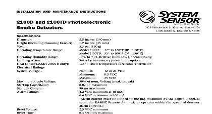
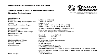
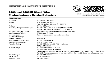
A Division of Pittway 3825 Ohio Avenue St Charles Illinois 60174 FAX 630 377 6495 AND MAINTENANCE INSTRUCTIONS and 2100T Photoelectronic Detectors including mounting bracket Temperature Range inches 140 mm inches 43 mm oz 150 g Humidity Range Alarm Sensor Model 2100T only Ratings Voltage Ripple Voltage Capacitance Current Ratings to 120 cid 176 F 0 cid 176 to 50 cid 176 C to 100 cid 176 F 0 cid 176 to 39 cid 176 C 2100 2100T to 93 Relative Humidity Noncondensing by momentary power interruption F Fixed Temperature Electronic Thermistor or 24 VDC VDC VDC of nom Voltage peak to peak m F maximum m A maximum VDC minimum at 10 mA VDC maximum at 100 mA current must be limited to 100 mA maximum by the control panel If used the RA400Z Remote Annunciator oper within the specified detector alarm currents Voltage Time Time VDC minimum seconds maximum seconds maximum after 60 second reset Installing thoroughly read System Sensor manual I56 407 for Proper Use of System Smoke Detectors which pro detailed information on detector spacing placement wiring and special applications Copies of this are available at no charge from System Sensor This manual should be left with the owner user this equipment This detector must be tested and maintained following NFPA 72 requirements The detector be cleaned at least once a year Description 2100 is a 2 wire photoelectronic smoke detector that a state of the art optical sensing chamber This detec is designed to provide open area protection and to be with compatible UL listed panels only Model 2100T a restorable built in fixed temperature 135 cid 176 F detector of these detectors is simplified by the use of a bracket and a plug in screw terminal block that be prewired to the system allowing the detector to be installed or removed for cleaning The detector sen can be tested in place using the MOD400R Test An LED on the detector provides a local visual in of the detector status If power is applied to the and it is functioning normally in standby the sta LED blinks every ten seconds The LED also latches on alarm 2100 and 2100T feature a visual indication that is required if the sensing chamber drifts out its sensitivity limits the LED ceases to blink detectors also include an output that allows an op Model RA400Z Remote Annunciator to be connected 1 Surface mounting of 2100 smoke detector 3 1 2 inch and 4 inch octagonal box responding properly in the event of a fire screw terminal block will accept 14 22 gauge wire best system performance all wiring should be installed separate grounded conduit do not mix fire system wir in the same conduit as any other electrical wiring pair may be used to provide additional protection extraneous electrical interference connections are made by stripping about 1 4 inch of from the end of the feed wire inserting the wire the appropriate terminal and tightening the screw to the wire in place 2100 and 2100T detector is supplied with a mounting that permits the detector to be mounted To a single gang box or Directly to a 3 1 2 inch or 4 inch octagonal box or To a 4 inch square electrical box by using a plaster ring Feature detector includes a tamper resistant feature that pre its removal from the bracket without the use of a tool make the detector tamper resistant remove the smaller by breaking it at the scribed line on the tamper resistant on the detector mounting bracket see Figure 2 then the detector To remove the detector from the bracket it has been made tamper resistant use a small screw to depress the tamper resistant tab located in the on the mounting bracket and turn the detector coun Installation Guidelines wiring must be installed in compliance with the Na Electrical Code applicable local codes and any spe requirements of the local authority having jurisdiction wire gauges should be used The conductors used to smoke detectors to control panels and accessory should be color coded to reduce the likelihood of errors Improper connections can prevent a system Sensor smoke detectors are marked with a compat identifier located as the last digit of a five digit code on the back of the product Connect detectors only compatible control units as indicated in System Sensor chart which contains a current list of UL compatible control units and detectors A copy of this is available from System Sensor upon request power from the control unit or initiating device cir before installing detectors Wire the plug in screw terminal block per Figure 3 and the terminal block into the detector Align the arrows on the detector with the arrows on the Turn the detector clockwise in the mounting bracket un bracket it clicks into place After all detectors have been installed apply power to control unit or initiating device circuits Test the detector as described in the following para Reset the detector at the system control panel Notify the proper authorities the system is in operation 2 2100 and 2100T smoke detector mounting bracket SLOT cid 13 TAB TO cid 13 DETECTOR RESISTANT TAB cid 13 CUT OFF SMALL TAB TO cid 13 ACTIVATE TAMPER RESIST cid 13 FEATURE 3 Wiring diagram for the 2100 and 2100T detector LISTED cid 13 RESISTOR cid 13 BY cid 13 CLASS A WIRING covers are an effective way to limit the entry of dust smoke detector sensing chambers However they may completely prevent airborne dust particles from enter the detector Therefore System Sensor recommends the of detectors before beginning construction or other producing activity Be sure to remove dust covers from sensors that were left in place during construction as of returning the system to service Before testing notify the proper authorities that smoke detector system is undergoing mainte and will temporarily be out of service Dis the zone or system undergoing maintenance prevent unwanted alarms must be tested after installation and following maintenance Test the 2100 as follows Test Switch A recessed test switch is located on the detector hous See Figure 4 Push and hold the recessed test switch with a 0.1 inch diameter tool such as an allen wrench or screwdriver The detector LED should light within 5 seconds 4 Top and side views showing position of test switch Test Module System Sensor Model No MOD400R MOD400R test module can be used with a DMM or voltmeter to check the detector sensitivity as de in the test module manual Smoke Entry Test a smoldering punk stick or cotton wick at the side the detector and gently blow smoke through the de until the unit alarms Direct Heat Method Model 2100T only Hair dryer of watts the heat toward either of the side thermistors the heat source about 12 inches from the detector order to avoid damage to the plastic The detector will only after it has had sufficient time to cool and the source has been momentarily interrupted smoke and heat detection testing are recommended verifying system protection capability detector that fails to activate with any of the above tests first be cleaned as outlined in the MAINTENANCE which follows If the detector still fails to activate it be returned for repair the proper authorities the system is back on line MODULE cid 13 TEST cid 13 RECESSED cid 13 WITH A cid 13 MAX DIAMETER TOOL