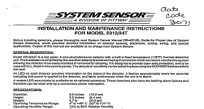
System Sensor 2112 24AITR Manual

File Preview
Click below to download for free
Click below to download for free
File Data
| Name | system-sensor-2112-24aitr-manual-8324560791.pdf |
|---|---|
| Type | |
| Size | 697.84 KB |
| Downloads |
Text Preview
INSTALLATION AND MAINTENANCE INSTRUCTIONS Smoke Detector with Heat and Integral Temp 3 Sounder 1 Wiring diagram for the 2112 24AITR detector Ohio Avenue St Charles Illinois 60174 FAX 630 377 6495 with all sounder models polarity must be observed on the power connections OBSERVE POLARITY LISTED POWER SHOWN 12 24V RESISTOR BY CLASS A WIRING including mounting bracket Temperature Range Humidity Range Alarm Signal Sensor Ratings Voltage nominal Ripple Voltage Current Current Voltage Time Time Relay Initiation and Auxiliary Relay Ratings Resistive Load Considerations inches 140 mm inches 52 mm oz 210 g to 100 0 to 38 to 93 Relative Humidity Noncondensing by momentary power interruption dBA minimum when in alarm or with supply polarity reversed Fixed Temperature Electronic Thermistor or 24 VDC VDC VDC of nom Voltage peak to peak maximum mA typical 60 mA max at 12V mA typical 65 mA max at 24V VDC minimum second maximum seconds maximum after 60 sec reset 12 24 VDC Relay changes only when the thermal alarm state is reached 30 VAC 30 VDC to the built in temporal pattern use these detectors only with a non coded power supply Installing thoroughly read the System Sensor manual I56 407 Guide for Use of System Smoke Detectors which provides detailed informa on detector spacing placement zoning wiring and special applica Copies of this manual are available at no charge from System This manual shall be left with the owner user of this equipment This detector must be tested and maintained following 72 requirements The detector should be cleaned at least once a Description 2112 24AITR is a 4 wire photoelectronic smoke detector that uses state of the art optical sensing chamber This detector also provides 135 fixed temperature heat detection The photoelectronic sensor is isolated from the fixed temperature heat sensor provid a self resetting local audible smoke alarm that does not alarm at the Only the fixed temperature heat sensor will cause the 2112 24AITR alarm at the panel and the relay to change its state Installation Guidelines wiring must be installed in compliance with the National Electrical applicable local codes and any special requirements of the local having jurisdiction Proper wire gauges should be used The used to connect smoke detectors to control panels and acces devices should be color coded to reduce the likelihood of wiring Improper connections can prevent a system from responding prop in the event of a fire addition a piezoelectric horn in each detector produces an interrupted dBA tone when the individual detector alarms or when the supply volt polarity is reversed In order for all detectors on a loop to sound when the panel the panel must reverse the supply voltage polarity to that upon alarm For panels that do not reverse the polarity during a reversing relay such as System Sensor RR 2 must be The RR 2 is designed to allow all the detectors in the same to sound when one of the detectors goes into alarm Some pan may require the use of programmable outputs Refer to System literature for further information on the RR 2 of this detector is simplified by the use of a mounting bracket a plug in screw terminal block that can be prewired to the system the detector to be easily installed or removed for cleaning The sensitivity can be tested in place using the MOD400R Test LED on the detector provides a local visual indication of the detector If power is applied to the detector and it is functioning normally in within the listed sensitivity range the status LED blinks every ten The LED also latches on in alarm the LED stops blinking the unit should be removed for maintenance inspection 2 Surface mounting of 2112 24AITR smoke detector on 1 and 4 inch octagonal box screw terminal block accepts 14 22 gauge wire For best system per all wiring should be installed in separate grounded conduit Do mix fire system wiring in the same conduit as any other electrical Twisted pair may be used to provide additional protection against interference detectors and alarm system control panels have specifications for loop resistance Consult the control panel specifications for the loop resistance allowed for the control panel being used before the detector loops connections are made by stripping about 1 4 inch of insulation from end of the feed wire inserting the wire into the appropriate terminal tightening the screw to secure the wire in place to Install Smoke Detectors As a minimum requirement smoke detectors must be installed accordance with the National Fire Protection Agency NFPA Standard which defines the standards for the National Fire Alarm Code National Protection Association Batterymarch Park MA 02269 9101 In addi observe all local and national building and electrical codes Detector Location 1 Recommended smoke detector protection for single residence with only one sleeping area ROOM BEDROOM 2112 24AITR detector is supplied with a mounting bracket that per the detector to


