System Sensor 2112 24R and 2112 24TR Manual

File Preview
Click below to download for free
Click below to download for free
File Data
| Name | system-sensor-2112-24r-and-2112-24tr-manual-5324789601.pdf |
|---|---|
| Type | |
| Size | 675.44 KB |
| Downloads |
Text Preview
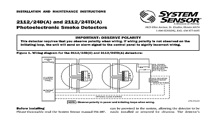
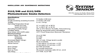
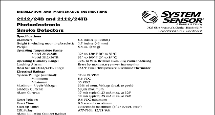
INSTALLATION AND MAINTENANCE INSTRUCTIONS and 2112 24TR Photoelectronic Detectors Ohio Avenue St Charles Illinois 60174 FAX 630 377 6495 1 Wiring diagram for the 2112 24R and 2112 24TR detector LISTED CLASS A WIRING POWER SHOWN 12 24V RESISTOR BY inches 140 mm including mounting bracket 1.7 inches 43 mm Temperature Range Model 2112 24R 32 to 120 0 to 49 2112 24TR 32 to 100 0 to 39 to 93 Relative Humidity Noncondensing by momentary power interruption Humidity Range Alarm Sensor Model 2112 24TR only 135 Fixed Temperature Electronic Thermistor Ratings Voltage nominal oz 190 g Ripple Voltage Current Current Voltage Time Time Relay Initiation and Auxiliary Relay Ratings Resistive Load or 24 VDC VDC VDC of nom Voltage peak to peak maximum mA typical 35 mA max at 12V mA typical 45 mA max at 24V VDC minimum seconds maximum seconds maximum after 60 sec reset 12 24 VDC 30 VAC 30 VDC 2 Surface mounting of 2112 24R and smoke detector on 31 and 4 inch box Installing thoroughly read the System Sensor manual I56 407 for Proper Use of System Smoke Detectors which pro detailed information on detector spacing placement wiring and special applications Copies of this are available at no charge from System Sensor This manual shall be left with the owner user of equipment This detector must be tested and maintained NFPA 72 requirements The detector should be at least once a year Description 2112 24R and 2112 24TR are 4 wire photoelectron smoke detectors that use a state of the art optical sens chamber The 2112 24TR also provides restorable fixed temperature heat detection The 2112 24TR unit is integrated with the photoelectronic of this detector is simplified by the use of a bracket and a plug in screw terminal block that be prewired to the system allowing the detector to be installed or removed for cleaning The detector sen can be tested in place using the MOD400R Test LED on the detector provides a local visual indication the detector status If power is applied to the detector it is functioning normally in standby within the listed ranges the status LED blinks every ten seconds LED also latches on in alarm the LED stops blinking the unit should be removed for and inspection 2112 24R and 2112 24TR detector is supplied with a bracket that permits the detector to be mounted To a single gang box or Directly to a 31 inch or 4 inch octagonal box or To a 4 inch square electrical box by using a plaster ring Directly to the ceiling using drywall anchors if permit by local codes and or the authority having jurisdic Feature detector includes a tamper resistant feature that pre its removal from the bracket without the use of a tool make the detector tamper resistant remove the smaller by breaking it at the scribed line on the tamper resistant on the detector mounting bracket see Figure 3 then the detector To remove the detector from the brack once it has been made tamper resistant use a small to depress the tamper resistant tab located in slot on the mounting bracket and turn the detector Installation Guidelines wiring must be installed in compliance with the Electrical Code applicable local codes and any requirements of the local authority having jurisdic Proper wire gauges should be used The conductors to connect smoke detectors to control panels and devices should be color coded to reduce the like of wiring errors Improper connections can prevent system from responding properly in the event of a fire screw terminal block accepts 14 22 gauge wire For system performance all wiring should be installed in grounded conduit Do not mix fire system wiring the same conduit as any other electrical wiring Twisted may be used to provide additional protection against interference 3 2112 24R and 2112 24TR smoke detector mounting bracket SLOT TAB TO DETECTOR RESISTANT TAB CUT OFF SMALL TAB TO ACTIVATE TAMPER RESIST FEATURE detectors and alarm system control panels have for allowable loop resistance Consult the panel specifications for the total loop resistance for the control panel being used before wiring the loops connections are made by stripping about 1 inch of from the end of the feed wire inserting the wire the appropriate terminal and tightening the screw to the wire in place power from the control unit or initiating device cir before installing detectors Wire the plug in screw terminal block per Figure 1 and the terminal block into the detector Align the arrows on the detector with the arrows on the After all detectors have been installed apply power to control unit or initiating device circuits Test the detector as described in TESTING Reset the detector at the system control panel Notify the proper authorities the system is in operation covers are an effective way to limit the entry of dust smoke detector sensing chambers However they may completely prevent airborne dust particles from enter the detector Therefore System Sensor recommends the of detectors before beginning construction or other producing activity Be sure to remove dust covers from sensors that were left in place during construction as of returning the system to service Before testing notify the proper authorities that smoke detector system is undergoing mainte and will be temporarily out of s