System Sensor 2151 for Special Applications

File Preview
Click below to download for free
Click below to download for free
File Data
| Name | system-sensor-2151-for-special-applications-8731459620.pdf |
|---|---|
| Type | |
| Size | 1.09 MB |
| Downloads |
Text Preview
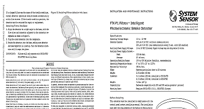
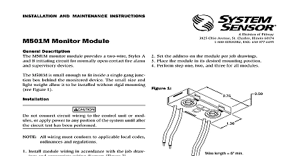
2151 Duct Smoke for Applications System Sensor 2151 low profile photoelectric smoke with a B114LP or B114LPBT base is listed to Laboratories 268A specifically for use in no air handling systems for 2151 B114LP B114LPBT Low profile smoke detector design Low standby current Two LEDs blink in standby Detector head plugs easily into base Field sensitivity metering of detector to meet the requirements NFPA 72 with the use of SENS RDR Designed for mounting on a standard electrical box Removable cover and insect screen for field cleaning Accepts 24 or 120V supply voltage 2151 can be used as a pendant mount detector in no flow air handling systems 0 3,000 FPM The pendant plenum 2151 is to be installed into a B114LP or B114LPBT This is the perfect combination for installation in ducts where air velocity is below 500fpm or for duct sizes as small as 8 in mounted in a standard electrical box within the duct the head allows easy removal from the base for quick and maintenance The 2151 heads can be combined with System Sensor B114LP 120VAC base or the B114LPBT 24VAC base Listings Photoelectric Detector Specifications Specifications air duct smoke detector shall be a System Sensor model 2151 Series Smoke detector listed to UL 268A specifically for use in air handling when used in conjunction with the B114LP or B114LPBT base The detector shall operate at air velocities up to 3,000 feet per minute shall be capable of local testing using a magnet test on the 2151 sensor head Specifications Temperature Range Humidity Range 4.22cm H oz 104 g to 120 0 to 49 to 93 relative humidity non condensing Plug In Detector Base Specifications Temperature Range inches 155mm 102 mm square box with or without plaster ring Minimum Depth 1.5 inches 38 mm Octagon Box Minimum Depth 1.5 inches 38 mm to applicable sensor Operating Temperature Range using the Base Sensor Cross Reference Chart systemsensor com Typical Wiring Diagrams Annunciator Used Used Annunciator used Supervisory Relay A Contacts Alarm Relay Base Terminals Function C C N O Alarm Relay N C C C Contacts A LEADS VAC 10 PANEL INITIATION LOOP 10 PANEL VAC 10 LEADS VAC INITIATION LOOP ABOVE DIAGRAM SHOWS NFPA REQUIRED WIRING OF SUPERVISED SCHEMATIC SHOWN BELOW FOR REFERENCE PANEL Typical Wiring Diagrams Annunciator Coil Used Annunciator Alarm Relay Base Terminals Function C C N O Alarm Relay N C C A C Contacts Relay A Contacts 10 VACrms DC VACrms DC 10 10 VACrms DC INITIATION LOOP ABOVE DIAGRAM SHOWS NFPA REQUIRED WIRING OF SUPERVISED SCHEMATIC SHOWN BELOW FOR REFERENCE DAMPER PANEL PANEL Information No photoelectric plug in detector order the base listed below VAC detector base detector base Ohio Avenue St Charles IL 60174 800 SENSOR2 Fax 630 377 6495 specifications subject to change without notice Visit systemsensor com current product information including the latest version of this data sheet System Sensor 1 12