System Sensor 2251TM Manual

File Preview
Click below to download for free
Click below to download for free
File Data
| Name | system-sensor-2251tm-manual-3591762804.pdf |
|---|---|
| Type | |
| Size | 644.01 KB |
| Downloads |
Text Preview
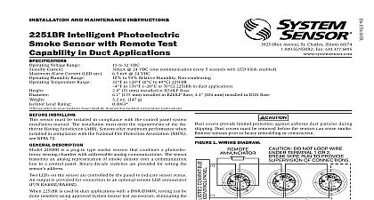
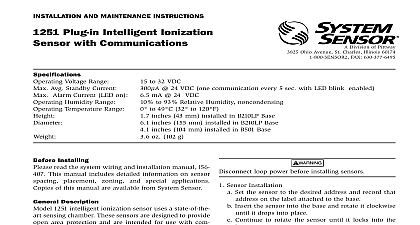
INSTALLATION AND MAINTENANCE INSTRUCTIONS Intelligent Smoke Sensor Division of Pittway Ohio Avenue St Charles Illinois 60174 FAX 630 377 6495 Voltage Range Current Alarm Current LED on Humidity Range Temperature Range Sensor Bases Available to 32 VDC 24 VDC one communication every 5 sec with LED blink enabled mA 24 VDC to 93 Relative Humidity noncondensing to 38 32 to 100 Fixed Temperature Electronic Thermistor inches 43 mm installed in B210LP Base inches 155 mm installed in B210LP Base inches 104 mm installed in B501 Base oz 142 g 200 500 Series bases are compatible Installing sensor must be installed in compliance with the con panel system installation manual The installation must the requirements of the Authority Having Jurisdiction Sensors offer maximum performance when installed compliance with the National Fire Protection Association see NFPA 72 Description 2251TM is a plug in type smoke sensor that com a photoelectronic sensing chamber and 135 fixed temperature heat detection The sensor uses communications to transmit smoke den and other information to the control panel Rotary switches are provided for setting the sensor Two LEDs on the sensor are controlled by the to indicate sensor status An output is provided for to an optional remote LED annunciator P N detector requires compatible addressable commu to function properly Connect this sensor to control panels only Sensor recommends spacing sensors in compliance NFPA 72 In low air flow applications with smooth space sensors 30 feet apart For specific informa regarding sensor spacing placement and special refer to NFPA 72 or the System Sensor Guide Proper Use of System Smoke Detectors available from Sensor P N I56 407 XX Instructions wiring must be installed in compliance with the Electrical Code applicable local codes and any requirements of the Authority Having Jurisdiction wire gauges should be used The installation wires be color coded to limit wiring mistakes and ease troubleshooting Improper connections will prevent system from responding properly in the event of a fire power from the communication line before sensors wiring must conform to applicable local codes ordi and regulations Wire the sensor base supplied separately per the diagram see Figure 1 Set the desired address on the sensor address switches Figure 2 Install the sensor into the sensor base Push the sensor the base while turning it clockwise to secure it in After all sensors have been installed apply power to the unit and activate the communication line Test the sensor s as described in the TESTING section this manual 1 Wiring diagram ANNUNCIATOR RETURN LOOP covers provide limited protection against airborne particles during shipping Dust covers must be before the sensors can sense smoke Remove sen prior to heavy remodeling or construction testing notify the proper authorities that the system undergoing maintenance and will temporarily be out of Disable the system to prevent unwanted alarms sensors must be tested after installation and periodical thereafter Testing methods must satisfy the Authority Jurisdiction AHJ Sensors offer maximum per when tested and maintained in compliance with 72 sensor can be tested in the following ways Functional Magnet Test P N M02 04 01 or M02 09 00 sensor can be functionally tested with a test mag The test magnet electronically simulates smoke in sensing chamber testing the sensor electronics and to the control panel Hold the test magnet in the magnet test area as shown Figure 3 The sensor should alarm the panel LEDs on the sensor are controlled by the panel to sensor status Coded signals transmitted the panel can cause the LEDs to blink latch on latch off Refer to the control panel technical doc for sensor LED status operation and delay to alarm Smoke Entry Aerosol Generator Gemini 501 entry testing should be performed immediately the magnet test Magnet test initiates an 10 minute period when the detector sig processing software routines are not active Failure to perform the magnet test will introduce a time delay the detector alarms GEMINI model 501 aerosol generator can be used smoke entry testing Set the generator to represent to 5 ft obstruction as described in the GEMI 501 manual Using the bowl shaped applicator apply until the panel alarms Direct Heat Method Hair Dryer of 1000 1500 watts hair dryer of 1000 1500 watts should be used to test thermistors Direct the heat toward either of the two holding the heat source approximately 12 from the detector in order to avoid damaging the housing The detector will reset only after it has sufficient time to cool Make sure both thermistors tested individually sensor that fails any of these tests should be cleaned as under CLEANING and retested fails after cleaning it must be replaced and returned repair testing is complete restore the system to normal and notify the proper authorities that the is back in operation is recommended that the detector be removed from its base to facilitate cleaning The detector is as follows Before removing the detector notify the proper that the smoke detector system is maintenance and will be temporarily of service Disable the zone or system under maintenance to prevent unwanted alarms the detector cover by prying away the four tabs with a small bladed screwdriver and then the cover from the base Vacuum the screen carefully without removing it If cleaning is required continue with Step 3 oth skip to Step 8 the screen assembly by pulling it straight out Figure 4 the sensing chamber cover by pulling it out the vaned chamber piece by vacuuming or out dust and particles the sensing chamber cover aligning the arrow the top with arrow on the printed circuit board replace the screen place it over the chamber turning it until it snaps into place the cover using the LEDs to align the cover then gently pushing it until it locks into place sure thermistors do not become bent under the detector Test the detector as described in TESTING Reconnect disabled circuits Notify the proper authorities that the system is back line 2 Rotary decade address switches 3 Test magnet position TEST STATUS 4 Sensor assembly REMOVAL refer to insert for the Limitations of Fire Alarm Systems Limited Warranty Sensor warrants its enclosed smoke detector to be free from in materials and workmanship under normal use and service for a of three years from date of manufacture System Sensor makes no express warranty for this smoke detector No agent representative or employee of the Company has the authority to increase or alter obligations or limitations of this Warranty The Company obligation this Warranty shall be limited to the repair or replacement of any part the smoke detector which is found to be defective in materials or work under normal use and service during the three year period com with the date of manufacture After phoning System Sensor toll number 800 SENSOR2 736 7672 for a Return Authorization number defective