System Sensor 2300TB Manual

File Preview
Click below to download for free
Click below to download for free
File Data
| Name | system-sensor-2300tb-manual-5872031964.pdf |
|---|---|
| Type | |
| Size | 687.04 KB |
| Downloads |
Text Preview
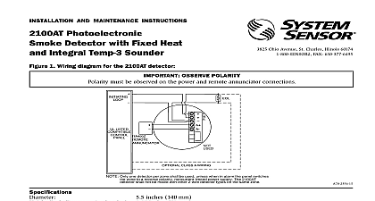
INSTALLATION AND MAINTENANCE INSTRUCTIONS MODEL 2300TB installing detectors please thoroughly read System Sensor Manual I56 407 XX Guide for Proper Use of System Smoke which provides detailed information on detector spacing placement zoning wiring and special applications Copies this manual are available at no charge from System Sensor DESCRIPTION 2300TB is a 2 wire combination smoke heat detector In addition to photoelectronic smoke detection two supervised thermistors provide restorable 135 fixed temperature heat detection The installation is simplified by the use of an bracket and a plug in screw terminal block which can be pre wired to the system allowing the detector to be easily or removed for cleaning It is designed to provide open area protection and to be used with UL listed compatible 2 control panels The detector sensitivity can be tested in place using the MOD400R field sensitivity test module 2300TB is listed to UL 268 and is a latching type system detector When latched in alarm the detector must be reset by momentary power interruption LED on the detector provides a local indication of the detector status If power is applied to the detector and the detector functioning properly in standby the status LED will blink every 10 seconds The detector performs a self test on its smoke chamber and internal electronics every 40 seconds If this test fails the detector stops blinking the status LED in and the LED will remain off In alarm the LED will be latched on continuously until the detector is reset detector provides an output for connection to an optional Remote Annunciator model RA400Z The Remote Annunciator to a single gang box and provides an LED indication of an alarm condition 5.5 inches 14 cm 2.5 inches 64 mm 0.7 lb 310 gm Temperature Range 0 to 38 C 32 to 100 F Humidity Range 10 to 90 Relative Humidity Non condensing Alarm Reset by momentary power interruption Feature Recessed test switch Air Velocity 3000 Ft Min 15 Meters Sec Nominal 3 Ft Sensor 135 Fixed Temperature Electronic Thermistor RATINGS Voltage nominal 12 or 24 VDC minimum 8.5 VDC maximum 35 VDC Ripple Voltage 30 of nom Voltage peak to peak Capacitance 0.02 maximum Current 120 maximum Ratings 4.2 VDC minimum at 10 mA 6.6 VDC maximum at 100 mA Alarm current must be limited to 100 mA maximum by the control panel If used the RA400Z Remote Annunciator operates within the specified detector alarm currents Voltage 2.5 VDC minimum Time 3 Sec maximum Time 34 Sec maximum After 60 Sec Reset I56 490 05 System Sensor 3825 Ohio Avenue St Charles Illinois 60174 1 800 SENSOR2 FAX 708 377 6495 1 2300TB Smoke Heat Detector 2300TB detector is supplied with a mounting bracket that permits the detector to be mounted To a single gang box or Directly to a 3 1 2 inch or 4 inch octagonal box or To a 4 inch square electrical box by using a plaster ring 2 2300TB smoke detector mounting bracket RESISTANCE detector includes a tamper resistant capability that prevents its removal from the bracket without the use of a tool To the detector tamper resistant remove the smaller tab by breaking it at the scribed line on the tamper resistant tab before the detector The tamper resistant tab is on the detector mounting bracket remove a tamper resistant detector from the bracket use a pocket screwdriver or similar tool to depress the tamper resis tab and turn the detector counterclockwise The tab is accessible through the slot on the mounting bracket INSTALLATION GUIDELINES wiring must be installed in compliance with the National Electrical Code applicable local codes and any special require of the local authority having jurisdiction Proper wire gauges should be used The conductors used to connect smoke to control panels and accessory devices should be color coded to reduce the likelihood of wiring errors Improper can prevent a system from responding properly in the event of a fire screw terminal block will accept 14 22 gauge wire For best system performance all wiring should be installed in sepa grounded conduit do not mix fire system wiring in the same conduit as any other electrical wiring Twisted pair may be to provide additional protection against extraneous electrical interference connections are made by stripping about 1 4 inch of insulation from the end of the feed wire inserting the wire into the terminal and tightening the screw to secure the wire in place