System Sensor 2400AT and 2400AIT Manual

File Preview
Click below to download for free
Click below to download for free
File Data
| Name | system-sensor-2400at-and-2400ait-manual-3125604789.pdf |
|---|---|
| Type | |
| Size | 754.99 KB |
| Downloads |
Text Preview
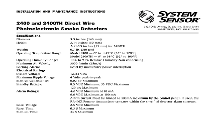
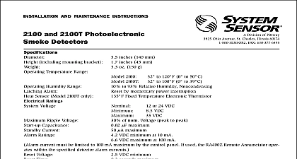
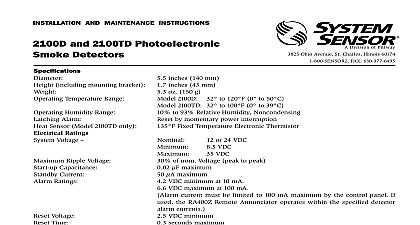
INSTALLATION AND MAINTENANCE INSTRUCTIONS and 2400AIT Direct Wire with Fixed Heat Detectors Division of Pittway 3825 Ohio Avenue St Charles Illinois 60174 FAX 630 377 6495 Diameter Velocity Temperature Humidity Indicator Alarm Signal Temperature Thermal Ratings Voltage Ripple Voltage Capacitance Time Limits Limits Current Supply Impedance Signal inches 140 mm inches 81 mm add 0.5 inches 13 mm for thermal units lb 310 g ft min 15 M s C to 38 cid 176 C 0 cid 176 to 100 cid 176 F to 93 Relative Humidity noncondensing State LED by Momentary Power Interruption minimum interrupted tone when in alarm or supply voltage polarity is reversed F 57 cid 176 C VDC Volts peak to peak m F Maximum Sec Maximum 32 VDC m A Maximum 100 m A Nominal at 10V 67mA at 32V 48mA at 24V at 10V 19mA at 32V 15mA at 24V Detector not in Alarm ohms Maximum 478 ohms Minimum Minimum in Alarm Installing thoroughly read the System Sensor manual I56 407 Guide for Proper Use of System Smoke Detectors This provides detailed information on detector spacing zoning wiring and special applications It is at no charge from System Sensor For installa in Canada refer to CAN ULC4 S524 Standard for the of Fire Alarm Systems and CEC Part 1 Sec 32 Description Sensor 2400AT and 2400AIT photoelectronic smoke listed to UL 268 provide open area protection are intended for use with UL listed compatible 2 wire panels The sensor in this detector operates on the scattering principle and features a unique photo optic chamber that optimizes smoke entry while mini the effects of ambient light interrupted 85 dBA tone when the individual detector or when the supply voltage polarity is reversed LED on each detector lights to provide a local alarm in and will remain on until the supply polarity is re A screw terminal is provided for a remote LED optional accessory RA400Z These detectors have the latching feature The alarm can be reset only momentary power interruption 2400 Series detector is supplied with a mounting kit to permit mounting in either of two ways Directly to a 3 or 4 inch octagonal 11 2 inch deep elec box See Figures 1 and 2 To a 4 inch square electrical box by using a plaster ring the mounting bracket kit supplied detectors also provide restorable 135 cid 176 F fixed tem heat detection The 2400AT heat detection unit is with the photoelectronic sensor while the heat detection unit is isolated from the photo smoke sensor and can be monitored separately addition a piezoelectric horn in each detector produces 72E defines the spacing requirements for smoke de Typically this is 30 feet when the detectors are in on a smooth ceiling However ALL installations comply with NFPA 72E and or special requirements the authority having jurisdiction 1 Flush mounting of detector on 4 inch box 2 Detector mounting bracket MAKE DETECTOR TAMPER RESISTANT OFF TAB EXTENSION SCRIBED LINE control units and detector combinations and is avail from System Sensor upon request Wiring Guidelines wiring must comply with the National Electrical Code the applicable local codes and any special require of the authority having jurisdiction using the proper gauges The conductors used to connect smoke detec to control panels and accessory devices should be to reduce the likelihood of wiring errors Im connections can prevent a system from responding in the event of a fire signal wiring wiring between interconnected detec wiring no smaller than AWG 18 is recommended The plates in the base can accept wire sizes up to 12 For best system performance the power and wires should be twisted pair and installed in separate conduit or shielded cable to protect the loop from electrical interference If a cable shield is pro the shield connection to and from the detector must made continuous by using wire nuts crimping or sol as appropriate for a reliable connection connections are made by stripping about 3 8 insula from the end of the wire sliding the bare end of the under the clamping plate and tightening the clamping screw Do NOT loop the wire under the terminals Sensor smoke detectors are marked with a compat identifier located as the last digit of a five digit code on the back of the product Connect detectors only compatible control units as indicated in System Sensor chart This chart contains a current list of UL covers provide limited protection against airborne particles during shipping Dust covers MUST be re before the smoke detectors can sense smoke Re sensors before beginning remodeling or heavy Feature Tamper Resistant Tab in the detector mounting can make the detector tamper resistant by making necessary to use a pocket screwdriver or similar tool to the detector from the bracket make the detector tamper resistant use needle nose pli to break the smaller tab at the scribed line on the Resistant Tab Figure 2 shows the location of this on the detector mounting bracket remove a detector from the bracket after it has been tamper resistant use a pocket screwdriver or other tool to depress the Tamper Resistant Tab in the slot the mounting bracket and rotate the detector counter Before testing notify the proper authorities that the detector system is undergoing maintenance therefore the system will be temporarily out service Disable the zone or system undergoing to prevent unwanted alarms 3 Wiring diagram for 2400AT detector with two wire control panel 4 Wiring diagram for 2400AIT detector with isolated thermal and two wire panels must be tested after installation and periodic System Sensor 2400AT and 2400AIT Smoke can be tested in the following five ways Before testing the detector check for the presence the flashing LED If it does not flash power has lost check the wiring or it is defective re for repair refer to the Warranty Recessed Test Switch Push and hold the recessed test switch with a 0.1 inch diameter tool such as a pocket screw The LED on the detector should light within 5 sec The p horn should also sound Calibrated Test Card R59 18 00 Remove the detector cover by placing a small bladed in the side slot of the detector cover it slightly until the cover can be turned coun for removal Insert the NO ALARM end of the test card fully into test slot see Figure 6 and slide it counterclock until it stops The detector should not alarm wait at least 20 alarm and annunciating the panel Replace the cover by gently rotating it clockwise until locks in place Test Module System Sensor Model No MOD400R MOD400R is used with an analog or digital voltme to check the detector sensitivity as described in the module manual Aerosol Generator Gemini 501 the generator to represent 4 Ft to 5 Ft obscura as described in the aerosol generator manual Using bowl shaped applicator apply aerosol until the unit Direct Heat Method Hair dryer of 1000 1500 watts the heat toward the bimetallic collector Hold the source about 12 inches from the detector in order to damage to the plastic When the heat rises to than 135 cid 176 F the detector will latch in alarm detector will reset only after it has had sufficient time cool and the power source has been temporarily inter Both smoke and heat detection testing are recom for verifying system protection capability Remove the test card by sliding it clockwise before re then repeat with the ALARM end of the test The LED should latch on within 20 seconds indicat that fail these tests should be cleaned as de under MAINTENANCE and retested If the detec still fail these tests they should be returned for repair the proper authorities the system is back on line 5 Bottom and side views showing position test switch