System Sensor 2412B, 2412THB, 2424, and 2424TH Manual

File Preview
Click below to download for free
Click below to download for free
File Data
| Name | system-sensor-2412b-2412thb-2424-and-2424th-manual-1879563420.pdf |
|---|---|
| Type | |
| Size | 681.75 KB |
| Downloads |
Text Preview
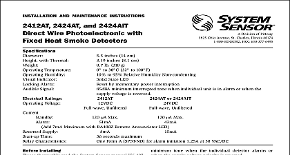
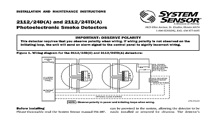
3825 Ohio Avenue St Charles Illinois 60174 FAX 630 377 6495 AND MAINTENANCE INSTRUCTIONS 2412THB 2424 and 2424TH Wire Photoelectronic Detectors 5.5 inches 14 cm 3.19 inches 81 mm Add 0.5 inches 1.3 cm for thermal units 0.7 lb 310 g Temperature Range 2412 and 2424 0 to 49 32 to 120 2412TH and 2424TH 0 to 38 32 to 100 Humidity Range 10 to 93 Relative Humidity Air Velocity 3000 Ft Min 15 M S Alarm Reset by momentary power interruption Ratings 2412 2424 Voltage 12 24 Voltage 11.3 20 17 29 Voltage 73 8 Current 120 120 Currents 35 21.3 77 40.6 alarm and auxiliary relay operate within the specified voltage ratings Time 34 34 Relay A77 716 A77 716 Time 0.3 0.3 Contacts resistive or inductive 60 power factor load A 2.0A 30VAC DC C 0.6A 110VDC 2.0A 30VDC 1.0A 125VAC 2.0A 30VAC Canadian installations relay contact rating is 2.0A 30VAC DC 4V Maximum Ripple Minimum Maximum Minimum Maximum Minimum Maximum Maximum Installing thoroughly read the System Sensor manual A05 Applications Guide for System Smoke Detectors provides detailed information on detector spacing zoning wiring and special applications Copies this manual are available at no charge from System For installation in Canada refer to CAN ULC Standard for the Installation of Fire Alarm Systems CEC Part 1 Sec 32 LED on each detector lights to provide a local alarm indi It flashes every ten seconds indicating that power applied to the detector The LED lights continuously in These detectors also have the latching alarm feature resets only by a momentary power interruption Description Sensor 2412 and 2424 photoelectronic smoke detec utilize state of the art optical sensing chambers These are designed to provide open area protection and be used with compatible UL listed 4 wire control panels The 2412 applies to 12 volt panels and operates at and the 2424 applies to 24 volt panels and operates 24VDC Operation and sensitivity can be tested in place 2412TH and 2424TH have the same specifications models 2412 and 2424 but in addition feature a built in temperature 135 thermal detection unit 1 I56 286 05R detector contains one set of Form A contacts for con to the alarm initiating circuit and one set of Form C contacts Supervision of detector power is accom by installing a Power Supervisory End of Line Relay A77 716 Series at the end of the detector power When power is applied to and through the detectors EOL Power Supervisory Module is energized Its relay close and provide a closed series circuit in the con panel alarm initiating loop A power failure or a break the detector power loop de energizes the EOL Module relay contacts open and trigger a trouble signal at the panel 1 Flush mounting of 2412 2424 smoke on 31 inch and 4 inch octagonal box 2 2412 2424 smoke detector mounting MAKE DETECTOR TAMPER RESISTANT OFF TAB EXTENSION SCRIBED LINE 2412 and 2424 detector is supplied with a mounting kit that permits the detector to be mounted Directly to a 31 inch or 4 inch octagonal 11 inch deep box see Figure 1 or To a 4 inch square electrical box by using a plaster ring the supplied mounting bracket kit Wiring Guidelines Refer to releasing device manufacturer installa instruction for proper connections wiring must be installed in compliance with the Electrical Code and all applicable local codes and special requirements of the authority having jurisdic using the proper wire size The conductors used to smoke detectors to control panels and accessory should be color coded to reduce the likelihood of errors Improper connections can prevent a system responding properly in the event of a fire signal wiring the wiring between interconnected it is recommended that the wire be no smaller AWG 18 However the screws and clamping plate in base can accommodate wire sizes up to AWG 12 The of twisted pair wiring for the power and loop is to minimize the effects of electrical interfer detectors and alarm system control panels have for allowable loop resistance Consult the panel manufacturer specifications for the total resistance allowed for the particular model control being used before wiring the detector loops For system supervision for terminals 1 2 7 and do not use looped wire under terminals Break run to provide system supervision of connec Contacts are shown in stand by mode and will in alarm condition connections are made by stripping about 3 inch of from the end of the wire sliding the bare end the wire under the clamping plate and tightening the plate screw Feature detector includes a tamper resistant feature that pre removal of the detector without the use of a tool To the detector tamper resistant break off the smaller at the scribed line on the Tamper Resistant Tab on the mounting bracket see Figure 2 then install the To remove the detector from the bracket once it been made tamper resistant use a small screwdriver to the tamper resistant tab located in the slot on the bracket and turn the detector counterclockwise removal 3 Wiring diagram for 2412 2424 series smoke detector used with 4 wire control panel 1 C A