System Sensor 2451 AND 2451TH Manual

File Preview
Click below to download for free
Click below to download for free
File Data
| Name | system-sensor-2451-and-2451th-manual-7960432185.pdf |
|---|---|
| Type | |
| Size | 637.61 KB |
| Downloads |
Text Preview
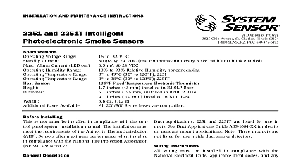
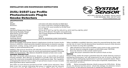
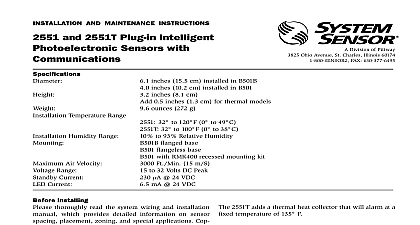
INSTALLATION AND MAINTENANCE INSTRUCTIONS and 2451TH Photoelectronic Smoke Detectors 2.4 inches 61 cm Add 0.5 inches 13 cm for thermal model 2451TH 4.0 inches 101 cm 0.5 lb 277 g Temperature Range 0 to 49 32 to 120 Humidity Range 10 to 93 Relative Humidity Air Velocity 3000 Ft Min 15 M S Alarm Reset by momentary power interruption Temperature Thermal 135 57 Ohio Avenue St Charles Illinois 60174 FAX 630 377 6495 Installing thoroughly read the System Sensor publication Applications Guide for System Smoke Detectors provides detailed information on detector spacing zoning wiring and special applications Copies this guide are available at no charge from System Sensor installations in Canada refer to CAN4 S524 Standard the Installation of Fire Alarm Systems and CEC Part 1 32 This manual should be left with the owner user this equipment This sensor must be tested and maintained following NFPA 72 requirements This sensor be cleaned at least once a year Description 2451 photoelectronic detectors utilize state of the art sensing chambers These detectors are designed to open area protection and to be used with compat UL listed control panels only Model 2451TH has the specifications as Model 2451 with the addition of built in fixed temperature 135 thermal detec unit The capability of plugging these detectors into variety of special bases makes them more versatile than direct wired models LEDs on each detector light to provide a local 360 alarm indication They flash every ten seconds indi that power is applied and the detector is operating The LEDs light continuously in alarm Remote annunciator capability is available as an optional These detectors also have the Latching Alarm The alarm can be reset only by a momentary power These detectors may be tested by activating internal reed switch with a magnet or by inserting a test card in a test slot after removing the detec cover 2451 has been approved for marine use in dry locations Underwriters Laboratory Inc The detector is to be used dry interior locations only Selection and Wiring Guide to the installation instructions for the Plug in Bases for base selection and wiring instructions Sensor has a variety of detector bases available for smoke detector This includes 2 wire applications with without relays and or current limiting resistors 4 wire 120VAC applications Note the 120VAC detector base not available in Canada bases are provided with screw terminals for power remote annunciator connections and relay contact if applicable The electrical ratings for each combination are also included in the base instructions 1 I56 277 10R Wiring must conform to applicable local codes control unit After all detectors have been installed apply power to and regulations Verify that all detector bases are installed that initiating device circuits have been tested and the wiring is correct Refer to detector base for testing procedure Test the detector using the magnet or the test card as under TESTING Reset the detector at the system control panel Notify the proper authorities that the system is back on power from initiating device circuits before detectors Install detectors a Place the detector into the detector base b Turn the detector clockwise until the detector drops covers can be used to help limit dust entry to the but they are not a substitute for removing the during building construction Remove any dust before placing system in service c Continue turning detector clockwise to lock it in place detectors are not to be used with detector guards the combination has been evaluated and found for that purpose Tamper Resistance This detector includes a tamper feature that prevents removal of the detector the use of a tool To make the detector tamper break off the smaller tab at the scribed line the tamper resistant tab on the detector mounting then install the detector To remove the detector the bracket once it has been made tamper resistant a pocket screwdriver or similar tool to depress the tab located in the slot on the mounting Then turn the detector counterclockwise until separates from the base 1 Bottom and side views showing position of test magnet C0495 00 2 I56 277 10R testing notify the proper authorities that the smoke system is undergoing maintenance and will tem be out of service Disable the zone or system maintenance to prevent unwanted alarms Direct Heat Test 2451TH only To test the bi metallic thermal collector aim a heat source as a low powered heat gun or blow dryer across the Hold the heat source about 12 inches 30 cm the detector to avoid damaging the plastic must be tested after installation and periodic To test the 2451 Before testing the detector check to ensure that LEDs are blinking If they are not the detector lost power check the wiring or it is defective for repair Test Magnet System Sensor model no M02 04 00 1 Place the magnet against the cover opposite the test slot to activate the test feature see Figure 2 The LEDs should latch on within 5 seconds indicating and annunciating the panel 2 When the temperature rises to greater than 135 the detector should latch into the alarm The collector automatically resets after the test the proper authorities that the detection system is on line that fail these tests should be cleaned as described MAINTENANCE and retested If the detectors still these tests they should be returned for repair HEAD COVER SLOT COVER SLOT Calibrated Test Card System Sensor no R59 18 00 1 Remove the detector cover by placing a small bladed in the side slot of the detector cover it slightly until the cover can be turned for removal 2 Insert the NO ALARM end of the test card fully into test slot see Figure 2 then slide it counterclock until it stops 3 Wait for at least 20 seconds The detector should NOT 4 Remove the test card by sliding it clockwise before then insert the ALARM end 5 The LEDs should latch on within 20 seconds indicat alarm and annunciating the panel 6 Put the cover back by gently rotating it clockwise it locks in place Test Module System Sensor no MOD400R The MOD400R is used with your DMM or voltmeter check t