System Sensor 2551HR Manual

File Preview
Click below to download for free
Click below to download for free
File Data
| Name | system-sensor-2551hr-manual-2681037459.pdf |
|---|---|
| Type | |
| Size | 616.56 KB |
| Downloads |
Text Preview
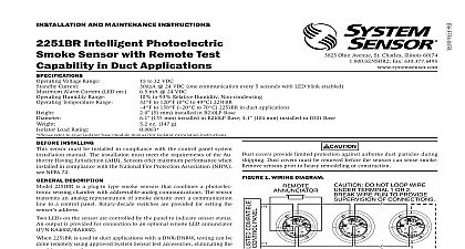
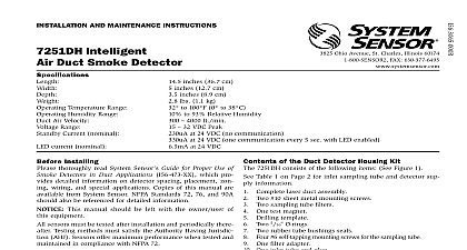
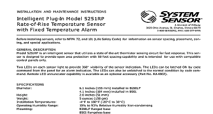
A Division of Pittway 3825 Ohio Avenue St Charles Illinois 60174 FAX 630 377 6495 AND MAINTENANCE INSTRUCTIONS Plug in Intelligent Sensors Communications Temperature Range Humidity Range Air Velocity Range Current Current inches 15.5 cm installed in B501B inches 10.2 cm installed in B501 inches 8.1 cm 0.5 inches 1.3 cm for thermal models ounces 272 g 32 to 120 F 0 to 49 C 32 to 100 F 0 to 38 C to 93 Relative Humidity flanged base flangeless base with RMK400 recessed mounting kit Ft Min 15 m S to 32 Volts DC Peak 24 VDC mA 24 VDC Installing thoroughly read the system wiring and installation which provides detailed information on sensor placement zoning and special applications Cop of these manuals are available from System Sensor This manual should be left with the owner user this equipment These detectors must be tested and main regularly following NFPA 72 requirements These should be cleaned at least once a year Description model 2551HR photoelectronic sensors utilize a state optical sensing chamber These sensors are de for use with duct housings DH500 and DH500AC only and to be used with compatible control panels Connect detectors only to compatible control units installation in Canada refer to CAN ULC S524 M86 for the Installation of Fire Alarm Systems and CEC 1 Sec 32 LEDs on each sensor light to provide a local 360 vis of the sensor indication The LEDs can be latched by code command from the panel for an alarm indica The LEDs can also be unlatched to the normal condi by code command Remote LED annunciator is available as an optional accessory part no Guide to the installation instructions for the particular plug base being used 1 for the B501B base D550 01 01 2 the B501 base D550 02 00 3 for the RMK400 used the B501 base D450 07 00 Bases are provided with terminals for power ground and remote annunciator see Figure 1 All wiring must conform to applicable local codes and regulations Verify that all sensor bases are installed and that wiring polarity is correct at each base power from the loop before installing sensors Install sensors Verify that the sensor type matches the type written the label on the base Set the sensor to a desired address and then write the on the label on the base Place the sensor into the sensor base 1 Wiring Diagram ANNUNCIATOR Do not loop wire under terminal 1 or 2 wire run to provide supervision of connections A OPTIONAL WIRING Turn the sensor clockwise until it drops into place Continue turning the sensor clockwise until it locks place will not detect smoke if dust cover is installed Tamper proof feature sensor bases include a tamper proof feature that activated prevents removal of the sensor without use of a tool See the installation instruction manual the sensor base for details in using this feature After all sensors have been installed apply power to the unit Test all sensors per the TESTING section of this manual testing notify the proper authorities that the smoke system is undergoing maintenance and therefore system will temporarily be out of service Disable the or system undergoing maintenance to prevent un alarms must be tested after installation and periodic main The sensor may be tested in the following ways Test Magnet Model No M02 04 00 Place the magnet against the cover opposite the test socket to activate the test feature see Figure 2 The LEDs should latch on within 10 seconds indicat alarm and annunciating the panel Test Module Model No MOD400R MOD400R is used with your DMM or voltmeter to the sensor sensitivity as described in the manual 2 Views showing position of test magnet model 2551HR shown MODULE the sensor sensitivity limits or the MOD400R do not appear on the back of the sensor the is not suitable for field sensitivity test of that unit Smoke Entry Test per NFPA 72 field test tool is the Gemini Model 501 aerosol gener Set the generator to represent 4 ft to 5 ft ob as described in the Gemini 501 manual Using bowl shaped applicator apply aerosol until unit If the Gemini unit is not available a punk cot wick or cigarette are acceptable means of generating to test all System Sensor ionization and photo sensors This test only verifies proper operation of the sen and is not used to test sensitivity 3 SLOT COVER SCREEN RS24 W O THERMAL W THERMAL testing detectors must be reset from the control Notify the proper authorities that the system is back line that fail these tests should be cleaned as described CLEANING and retested If the sensors still fail these they should be returned for repair cover is not a substitute for removing sensor during construction or heavy remodeling Cover only helps dust entry the Sensor Before cleaning notify the proper authorities that smoke sensor system is undergoing mainte and will temporarily be out of service Dis the loop or system undergoing maintenance to unwanted alarms is recommended that the sensor be removed from its base to facilitate easier cleaning see Figure 3 sensor is cleaned as follows Remove the sensor cover by placing a small bladed in the side slot of the sensor cover twisting slightly until the cover can be turned counterclockwise removal Vacuum the screen carefully without removing it If fur cleaning is required continue with Step 3 otherwise to Step 6 Remove the screen by pulling it straight out Vacuum the Clean the vaned chamber piece by vacuuming or blow out dust and particles To replace the screen orient it so that the arrow on top with the field test slot on the base of the detector push the screen onto the base making sure it tightly to the chamber Replace the cover by gently rotating it clockwise until it in place Limitations of Property Protection Smoke Detectors smoke detector is designed to activate and initiate emergency ac but will do so only when it is used in conjunction with an authorized alarm system This detector must be installed in accordance with standard 72 detectors will not work without power AC or DC powered detectors will not work if the power supply is cut off detectors will not sense fires which start where smoke does not the detectors Smoldering fires typically do not generate a lot of which is needed to drive the smoke up to the ceiling where the detector is usually located For this reason there may be large de in detecting a smoldering fire with either an ionization type detector a photoelectric type detector Either one of them may alarm only after has initiated which will generate the heat needed to drive the to the ceiling from fires in chimneys in walls on roofs or on the other side of a door s may not reach the smoke detector and alarm it A detector detect a fire developing on another level of a building quickly or at For these reasons detectors shall be located on every level and in bedroom within a building detectors have sensing limitations too Ionization detectors and detectors are required to pass fire tests of the flaming and type This is to ensure that both can detect a wide range of of fires Ionization detectors offer a broad range of fire sensing capa but they are somewhat better at detecting fast flaming fires than smoldering fires Photoelectric detectors sense smoldering fires better flaming fires which have little if any visible smoke Because fires de in different ways and are often unpredictable in their growth nei type of det