System Sensor 2W-MOD2 Manual

File Preview
Click below to download for free
Click below to download for free
File Data
| Name | system-sensor-2w-mod2-manual-2986435170.pdf |
|---|---|
| Type | |
| Size | 1.07 MB |
| Downloads |
Text Preview
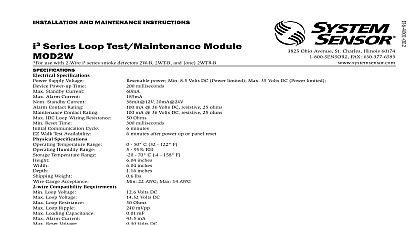
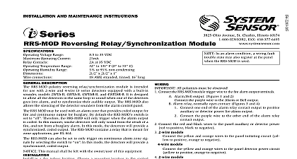
I AND MAINTENANCE INSTRUCTIONS Test Maintenance Module 2W MOD2 Installing information is included as a quick reference installa guide Refer to the control panel installation manual detailed system information If the modules will be in in an existing operational system inform the opera and local authority that the system will be temporarily of service Disconnect power to the control panel before the modules This manual shall be left with the owner user of equipment Description 2W MOD2 allows a control panel to receive a for signal from two i3 series smoke detec model numbers 2W 2WT 2WTA and 2WTR module uses a form C zone relay to initiate of sen and trouble a form A zone alarm relay and second form A zone relay to indicate loop fault see Figure An EZ Walk Test puts all detectors on the loop into a Walk mode for easy verification of detector loop wiring 1 relay form C relay form A trouble relay form A trouble trouble trouble and trouble and loop trouble and Maintenance Freeze OFF Location 7 N O 8 Common 9 N C connected terminals and 11 connected between 10 and 12 2 Module front view LED LED LED Walk Test LED on the module provide a local visual indica of the module status es maintenance module allows two wire smoke detectors to used on any electrically compatible four wire control panel 3825 Ohio Avenue St Charles Illinois 60174 FAX 630 377 6495 If two i3 detectors are used in conjunction a style D initiating circuit the 2W must be to provide that capability Ground fault on a mod two wire loop can be indicated at a control panel if control panel is capable of ground fault detection on power supply to the module and meets NFPA 72 ground indication requirements for initiating device circuits installer must verify that capability 3 Module LED modes COLOR LED 1 sec ON 1 sec OFF LED 1 sec ON 1 sec OFF on Detectors loop do not have capability on One or more on loop have capability not applied or not operating on loop in alarm or more detectors of sensitivity or in Trouble on loop not alarm maintenance Freeze Trouble LED 0.5 sec ON 0.5 sec OFF wiring fault Walk Test mode wiring normal module has loop trouble restoration detection If the trouble open loop doesn exist any more the mod will restore to standby condition with a maximum delay 1 minute There is no delay in loop trouble detection an alarm occurs while the module is indicating mainte the alarm will supercede maintenance the green LED remains ON no blinking three minutes af applying power it means that the module has determined no detector on its loop has communication capability this condition the detectors are still capable of initiating and loop trouble at the module However maintenance freeze trouble will not be indicated at the module and walk test will not be available If i3 detectors are installed the loop verify wiring and system operation NFPA loop Style D wiring the EOL resistor is provided to the module An external EOL resistor must be connected at the last detector on the loop see Fig 5 7 Requirements 2W MOD2 is marked with a compatibility zone identi as the last digit of a 5 digit code on the back of the unit ensure proper operation this module shall be connected compatible two wire smoke detectors or the alarm con of four i3 series detectors only Consult System 2 wire compatibility guide 4 Mounting module Diagram module wiring in accordance with appropriate wir diagrams Figures 5 7 Reset is performed through inputs 1 and 2 5 The Module Wiring maintenance signal is to a separate zone CIRCUITS ARE SUPERVISED MUST BE POWER LIMITED listed smoke Do not mix on the same loop one 2WTR per loop one 2WTA per loop used with the RRS Panel or Zone Zone EOL EOL Style D wiring K EOL must not be for Style D 6 The Module Wiring maintenance signal is at the panel as a fire trouble CIRCUITS ARE SUPERVISED MUST BE POWER LIMITED listed smoke Do not mix on the same loop one 2WTR per loop one 2WTA per loop used with the RRS Panel or Zone EOL Style D wiring K EOL must not be for Style D 7 The Module Wiring two wire detectors to panel conversion CIRCUITS ARE SUPERVISED MUST BE POWER LIMITED listed smoke Do not mix on the same loop one 2WTR per loop one 2WTA per loop used with the RRS Panel or Zone Style D wiring K EOL must not be for Style D EOL in a dry indoor location The 2W MOD2 Mainte Module mounts directly to 4 inch square electrical supplied by installer The box must have a mini depth of 2 1 8 inches Secure module to box as shown Figure 4 Installation Guidelines wiring must be installed in compliance with the Na Electrical Code applicable state and local codes and special requirements of the local authority having ju AHJ wire gauges should be used The conductors used connect the module to the alarm control panel smoke and accessory devices should be color coded to the likelihood of wiring errors Improper connec can prevent a system from responding properly in the of a fire screw terminals in the mounting base will accept 14 24 wire For best system performance all wiring should installed in separate grounded conduit do not mix fire system wiring in the same conduit as any other elec wiring Twisted pair may be used to provide addi protection against extraneous electrical interference connections are made by stripping about 1 4 inch of from the end of the feed wire inserting it into proper terminal and tightening the screw to secure the in place power from alarm control unit or initiating device before installing modules all modules have been installed notify the proper au that the system is in operation Before testing notify the proper authorities that is being performed and the system will be out of service Disable the zone or system un maintenance to prevent any unwanted alarms must be tested after installation and following pe maintenance Testing should be performed at least a year at Power Up or Reset minutes after power up the module will check for high maintenance low maintenance and trouble with each communication spaced 1 minute If a valid response to the communication check is the module will check for freeze trouble every hours low and high maintenance every 24 hours and recheck communication every 24 hours Whenever the fails to receive a valid response to the communica checks it will verify the result with another commu check one minute later If it still fails t