System Sensor 5251B, 5251H, and 5251RB Manual

File Preview
Click below to download for free
Click below to download for free
File Data
| Name | system-sensor-5251b-5251h-and-5251rb-manual-5419726308.pdf |
|---|---|
| Type | |
| Size | 1.27 MB |
| Downloads |
Text Preview
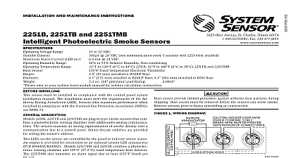
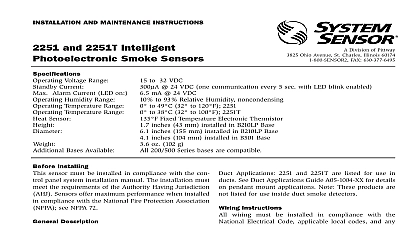
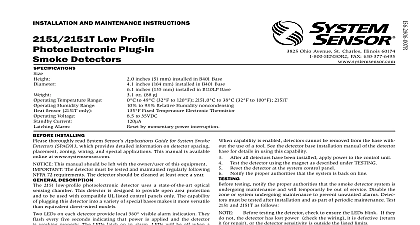
INSTALLATION AND MAINTENANCE INSTRUCTIONS 5251RB and 5251H Plug In Temperature Sensors Temperatures Humidity Range Range Current Current Temperature Rating of Rise Detection inches 155 mm installed in B210LP 4.1 inches 104 mm installed in B501 inches 51 mm ounces 137 gm to 100 to 38 5251B and 5251RB to 150 to 66 5251H to 93 Relative Humidity Non condensing flanged base B501 flangeless base B501 with RMK400 recessed mounting kit to 32 Volts DC Peak 24 VDC one communication every 5 seconds with LED blink enabled mA 24 VDC 57 5251B and 5251RB 190 88 5251H to greater than 15 5251RB 3825 Ohio Avenue St Charles Illinois 60174 FAX 630 377 6495 INSTALLING sensor must be installed in compliance with the control panel system manual The installation must meet the requirements of the Au Having Jurisdiction AHJ Sensors offer maximum performance when in compliance with the National Fire Protection Association NFPA NFPA 72 read the system wiring and installation manual thoroughly This man provides detailed information on sensor spacing placement zoning and applications Copies of these manuals are available from System Sen DESCRIPTION 5251B 5251RB and 5251H are intelligent sensors that utilize a state of thermistor sensing circuit for fast response These sensors are designed provide open area protection with 50 foot spacing capability as approved by 521 Model 5251B is a fixed temperature sensor with 135 fixed tempera alarm Model 5251RB is a rate of rise temperature sensor with 135 fixed alarm Model 5251H is a high temperature sensor with 190 temperature alarm LEDs on each sensor light to provide 360 visibility of the sensor indica The LEDs can be latched ON by code command from the panel for an indication The LEDs can also be unlatched to the normal condition code command Remote LED annunciator capability is available as an op accessory Part No RA400Z RA100Z 5251B 5251RB and 5251H require compatible addressable commu to function properly Connect these sensors to listed compatible panels only 5251RB Heat detectors are sold in the European Community for use in applications in conjunction with sprinkler systems They must not be in Europe as part of an EN54 fire detection and alarm system GUIDE wiring must be installed in compliance with the National Electrical Code local codes and the Authority Having Jurisdiction Proper wire should be used The installation wires should be color coded to limit mistakes and ease system troubleshooting Improper connections will a system from responding properly in the event of a fire power from the communication line before installing sensors Wire the sensor base supplied separately per the wiring diagram see 1 Set the desired address on the sensor address switches see Figure 2 Install the sensor into the sensor base Push the sensor into the base turning it clockwise to secure it in place After all sensors have been installed apply power to the control unit and the communication line Test the sensor s as described in the TESTING section of this manual RESISTANCE sensor bases have a tamper resistant capability When this capability is sensors cannot be removed from the base without the use of a small or other similar tool Refer to the sensor base installation instruc manual for details in using this capability testing notify the proper authorities that the system is undergoing and will temporarily be out of service Disable the system to unwanted alarms sensors must be tested after installation and periodically thereafter Test methods must satisfy the Authority Having Jurisdiction AHJ Sensors maximum performance when tested and maintained in compliance with 72 The sensor may be tested in the following ways TEST MAGNET MODEL NO M02 04 Place the magnet against the cover in the magnet test area as shown Figure 3 to activate the test feature The LEDs should latch ON within 10 seconds indicating alarm and the panel Reset the detector at the system control panel DIRECT HEAT METHOD HAIR DRYER OF 1000 1500 WATTS From the side of the detector direct the heat toward the sensor Hold heat source about 6 inches 15cm away to prevent damage to the during testing The LEDs on the detector should light when the temperature at the reaches the alarm set point If the LEDs fail to light check power to the detector and the wiring in the detector base Reset the detector at the system control panel that fail these tests should be cleaned as described under MAIN and retested If the detectors still fail these tests they should be for repair Before cleaning notify the proper authorities that the system is under maintenance and therefore the system will temporarily be out of ser Disable the loop or system undergoing maintenance to prevent unwanted is recommended that the sensor be removed from its mounting base for cleaning and that sensors be cleaned at least once a year Use a vacuum to remove dust from the sensing chamber DO NOT LOOP WIRE TERMINAL 1 OR 2 WIRE RUN TO PROVIDE OF CONNECTIONS 2 ROTARY DECADE ADDRESS SWITCHES 0 0 1 A OPTIONAL WIRING 3 VIEWS SHOWING POSITION OF TEST MAGNET 4 MAGNET CLASSIFICATION ratings are for installations which must comply with FM 3210 RTI RTI RTI refer to insert for the Limitations of Fire Alarm Systems LIMITED WARRANTY Sensor warrants its enclosed heat detector to be free from defects in materials workmanship under normal use and service for a period of three years from date manufacture System Sensor makes no other express warranty for this heat detector agent representative dealer or employee of the Company has the authority to in or alter the obligations or limitations of this Warranty The Company obligation this Warranty shall be limited to the repair or replacement of any part of the heat which is found to be defective in materials or workmanship under normal use service during the three year period commencing with the date of manufacture phoning System Sensor toll free number 800 SENSOR2 736 7672 for a Return number send defective units postage prepaid to Honeywell 12220 Rojas Suite 700 El Paso TX 79936 USA Please include a note describing the malfunc and suspected cause of failure The Company shall not be obligated to repair or units which are found to be defective because of damage unreasonable use or alterations occurring after the date of manufacture In no case shall the be liable for any consequential or incidental damages for breach of this or any Warranty expressed or implied whatsoever even if the loss or damage is caused by Company negligence or fault Some states do not allow the exclusion or limitation of or consequential damages so the above limitation or exclusion may not apply you This Warranty gives you specific legal rights and you may also have other rights vary from state to state STATEMENT device complies with part 15 of the FCC Rules Operation is subject to the following two conditions 1 This device may not cause harmful interference and 2 this device must any interference received including interference that may cause undesired operation This equipment has been tested and found to comply with the limits for a Class B digital device pursuant to Part 15 of the FCC Rules These limits are designed to provide protection against harmful interference in a residential installation This equipment generates uses and can radiate radio frequency energy and if not installed and used accordance with the instructions may cause harmful interference to radio communications However