System Sensor 5251P Manual

File Preview
Click below to download for free
Click below to download for free
File Data
| Name | system-sensor-5251p-manual-9836201457.pdf |
|---|---|
| Type | |
| Size | 606.44 KB |
| Downloads |
Text Preview
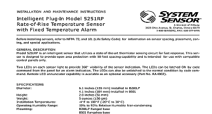
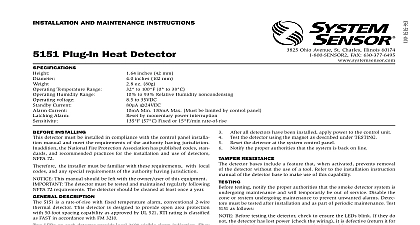
INSTALLATION AND MAINTENANCE INSTRUCTIONS Plug In Model 5251P Temperature Sensor Division of Pittway 3825 Ohio Avenue St Charles Illinois 60174 FAX 630 377 6495 installing sensors refer to NFPA 72 and 101 Life Safety Code for information on sensor spacing placement zon and special applications DESCRIPTION 5251P is an intelligent sensor that utilizes a state of the art thermistor sensing circuit for fast response This sensor designed to provide open area protection with 50 foot spacing capability and is intended for use with compatible con panels only LEDs on each sensor light to provide 360 visibility of the sensor indication The LEDs can be latched ON by code from the panel for an alarm indication The LEDs can also be unlatched to the normal condition by code com Remote LED annunciator capability is available as an optional accessory Part No RA400Z Temperatures Humidity Range Range Current Current Temperature Rating inches 155 mm installed in B210LP inches 104 mm installed in B501 inches 51 mm ounces 150 gm to 100 F 20 C to 38 C to 93 Relative Humidity Non condensing flanged base flangeless base with RMK400 recessed mounting kit to 32 Volts DC Peak 24 VDC one communication every 5 seconds with LED blink enabled mA 24 VDC 57 C GUIDE to the installation instructions for the particular plug in base being used 1 for the B210LP base D250 01 00 2 for B501 base D550 02 00 3 for the RMK400 used with the B501 base D450 07 00 Bases are provided with screw ter for power ground and remote annunciator connections See Figure 1 All wiring must conform to applicable local codes ordinances and regulations Verify that all sensor bases are installed and that the wiring polarity is correct at each base Disconnect the power from the loop before installing sensors Install Sensors Verify that the sensor type matches the type written on the label in the base Set the sensor to a desired address and then write the address on the label on the base Place the sensor into the sensor base Turn the sensor clockwise until it drops into place Continue turning the sensor clockwise to lock it in place ANNUNCIATOR Do not loop wire under terminal 1 or 2 wire run to provide supervision of connections A OPTIONAL WIRING 1 Tamper Resistance sensor bases have a tamper resistant capability When this capability is enabled sensors cannot be removed from base without the use of a small screwdriver or other similar tool Refer to the sensor base installation instruction for details in using this capability After all sensors have been installed apply power to the control unit Test the sensor by placing a small magnet against the sensor plastic as shown in Figure 2 The alarm level should be in the panel and the LED controlled by communication command from the panel The reset of the sensor LED is controlled by communication command from the panel must be tested after installation and periodic maintenance The sensor may be tested in the following ways Test Magnet Model No M02 04 Place the magnet against the cover in the magnet test area as shown in Figure 2 to activate the test feature The LEDs should latch ON within 10 seconds indicating alarm and annunciating the panel Reset the detector at the system control panel Test sensitivity from the control panel Direct Heat Method Hair dryer of 1000 1500 watts From the side of the detector direct the heat toward the sensor Hold the heat source about 6 inches 15cm away to damage to the cover during testing The LEDs on the detector should light when the temperature at the detector reaches 135 F 57 C If the LEDs fail light check the power to the detector and the wiring in the detector base Reset the detector at the system control panel that fail these tests should be cleaned as described under MAINTENANCE and retested If the detectors still fail tests they should be returned for repair TEST MARKER 2 Views showing position of test magnet Before cleaning notify the proper authorities that the system is undergoing maintenance and therefore the system temporarily be out of service Disable the loop or system undergoing maintenance to prevent unwanted is recommended that the sensor be removed from its mounting base for easier cleaning and that sensors be cleaned at once a year Use a vacuum cleaner to remove dust from the sensing chamber See Figure 3 3 refer to insert for the Limitations of Fire Alarm Systems Limited Warranty Sensor warrants its enclosed heat detector to be free from defects materials and workmanship under normal use and service for a period three years from date of manufacture System Sensor makes no other warranty for this heat detector No agent representative dealer or of the Company has the authority to increase or alter the obliga or limitations of this Warranty The Company obligation of this shall be limited to the repair or replacement of any part of the detector which is found to be defective in materials or workmanship normal use and service during the three year period commencing the date of manufacture After phoning System Sensor toll free 800 SENSOR2 736 7672 for a Return Authorization number defective units postage prepaid to System Sensor Repair Depart RA 3825 Ohio Avenue St Charles IL 60174 Please a note describing the malfunction and suspected cause of failure Company shall not be obligated to repair or replace units which are to be defective because of damage unreasonable use modifica or alterations occurring after the date of manufacture In no case the Company be liable for any consequential or incidental damages breach of this or any other Warranty expressed or implied whatsoever if the loss or damage is caused by the Company negligence or fault states do not allow the exclusion or limitation of incidental or conse damages so the above limitation or exclusion may not apply to This Warranty gives you specific legal rights and you may also have rights which vary from state to state Statement device complies with part 15 of the FCC Rules Operation is subject to the following two conditions 1 This device may not cause harmful interfer and 2 this device must accept any interference received including interference that may cause undesired operation This equipment has been tested and found to comply with the limits for a Class B digital device pursuant to Part 15 of the FCC Rules These limits designed to provide reasonable protection against harmful interference in a residential installation This equipment generates uses and can radio frequency energy and if not installed and used in accordance with the instructions may cause harmful interference to radio commu However there is no guarantee that interference will not occur in a particular installation If this equipment does cause harmful interfer to radio or television reception which can be determined by turning the equipment off and on the user is encouraged to try to correct the by one or more of the following measures Reorient or relocate the receiving antenna Increase the separation between the equipment and receiver Connect the equipment into an outlet on a circuit different from that to which the receiver is connected Consult the dealer or an experienced radio TV technician for help 2000 System Sensor