System Sensor 5451 Install and Maint Instructions

File Preview
Click below to download for free
Click below to download for free
File Data
| Name | system-sensor-5451-install-and-maint-instructions-4730261859.pdf |
|---|---|
| Type | |
| Size | 708.63 KB |
| Downloads |
Text Preview
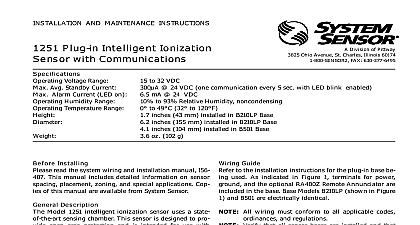
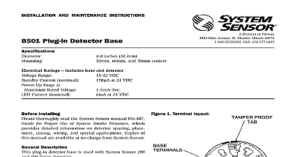
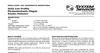
INSTALLATION AND MAINTENANCE INSTRUCTIONS Plug in Rate of Rise Detector with Temperature Alarm SENSOR Division of Pittway 3825 Ohio Avenue St Charles Illinois 60174 FAX 630 377 6495 Temperatures Humidity Range Alarm Voltage Current inches 104 mm inches 53 mm ounces 150 g to 100 cid 176 F 0 cid 176 to 38 cid 176 C to 93 Relative Humidity by momentary power interruption F 57 cid 176 C Fixed or 15 cid 176 F min rate of rise VDC m A Installing detector must be installed in compliance with the panel installation manual and meet the require of the authority having jurisdiction In addition the Fire Protection Association has published codes and recommended practices for the installation use of detectors NFPA 72 installation in Canada refer to CAN ULC S524 Stan for the Installation of Fire Alarm Systems and CEC 1 Sec 32 the installer must be familiar with these re with local codes and any special require of the authority having jurisdiction This manual should be left with the owner user this equipment This detector must be tested and main regularly following NFPA 72 requirements The de should be cleaned at least once a year Description 5451 is a rate of rise with fixed temperature alarm detector utilizing a state of the art dual thermistor circuit These detectors are designed to provide area protection with 50 foot spacing capability and to be used with compatible control panels only LEDs on each detector light to provide 360 cid 176 visibility the detector indication Remote LED annunciator capa is provided as standard and the RA400Z remote LED is available as an optional accessory Selection and Wiring Guide to the installation instructions for the plug in detector for base selection and wiring instructions System has available a variety of detector bases for these detectors including 2 wire applications with and relays and or current limiting resistors for use with panels that require one This detector is only to be with 400 and 400B series bases the System Sensor plug in base to be used with the following the instructions in the base manual Manuals Online All wiring must conform to applicable installation and regulations Verify that all detector bases are installed that the circuits have been tested and that wiring is correct Refer to detector base for testing procedure the power from initiating device circuits before detectors Install Detectors place control unit After all detectors have been installed apply power to Test the detector using the magnet as described under Reset the detector at the system control panel Notify the proper authorities that the system is in opera Resistance detector bases include a feature that when activated removal of the detector without the use of a tool to the installation instruction manual of the detector to make use of this capability testing notify the proper authorities that the heat system is undergoing maintenance and therefore system will temporarily be out of service Disable the or system undergoing maintenance to prevent un alarms must be tested after installation and periodic The 5451 may be tested as follows module socket See Figure 1 The LEDs on the detector should light within 10 sec If the LEDs fail to light check the power to the and the wiring in the detector base Reset the detector at the system control panel Insert the detector into the detector base Turn the detector clockwise until the detector drops Test Magnet System Sensor Model No M02 04 Continue turning detector clockwise to lock it in Position the magnet against the cover opposite the 1 Bottom and Side Views Showing Position of Test Magnet MODULE Manuals Online Test Module System Sensor Model No MOD400 or MOD400 or MOD400R is used with a DMM or volt to check the detector sensitivity as described in module manual Direct Heat Method Hair dryer of 1000 1500 watts the side of the detector direct the heat toward the Hold the heat source about 15 cm away to pre damage to the cover during testing a detector goes into alarm it will reset only if the has cooled and if its power is momentarily Check the control panel being used to whether the RESET switch or some auxiliary device or control momentarily cuts power to the detector loop that fail these tests should be cleaned as de under MAINTENANCE and retested If the detec still fail these tests they should be returned for repair 5451 detector has been designed to be as maintenance as possible Normal air borne dust however can accu on the detector sensing elements and cause them become less sensitive All detectors should be tested and at least once a year and those in dustier areas be tested and cleaned more often Detectors must be cleaned and tested immediately after a fire cleaning notify the proper authorities that the sys is undergoing maintenance and therefore the system temporarily be out of service Disable the loop or sys undergoing maintenance to prevent unwanted alarms Remove detector from mounting base Use a vacuum cleaner to remove dust from the sensing Reinstall the detector Test detector as described under TESTING Manuals Online Limitations of Property Protection Heat Detectors heat detector is designed to activate and initiate emergency action will do so only when it is used in conjunction with an authorized fire system This detector must be installed in accordance with NFPA 72 detectors will not work without power AC or DC powered smoke will not work if the power supply is cut off for any reason detectors are designed to protect property not life They do not early warning of fire and cannot detect smoke gas combustion or flame They alarm when temperatures at the heat detector 57 cid 176 C 135 cid 176 F Given the rapid growth of certain types of fires heat cannot be expected to provide adequate warning of fires from smoking in bed inadequate fire protection practices explosions escaping gas improper storage of flammable liquids cleaning solvents other safety hazards or arson detectors do not always detect fires because the fire may be a low heat type producing smoke or because they not be near where the fire occurs or because the heat of the fire bypass them Heat detectors will not detect smoke gas flames or particles detectors are components in professionally installed fire alarm They will not function if they have been improperly wired the fire alarm system or if power to them is cut off for any reason detectors cannot last forever They should be tested and maintained the instructions in this manual To be safe they should be after they have been installed for 15 years to NFPA 72 for application Limited Warranty Sensor warrants its enclosed heat detector to be free from defects materials and workmanship under normal use and service for a period three years from date of manufacture System Sensor makes no other warranty for this heat detector No agent representative dealer or of the Company has the authority to increase or alter the obliga or limitations of this Warranty The Company obligation of this shall be limited to the repair or replacement of any part of the detector which is found to be defective in materials or workmanship normal use and service during the three year period commencing the date of manufacture After phoning System Sensor toll free 800 SENSOR2 736 7672 for a Return Authorization number defective units postage prepaid to System Sensor Repair Depart RA 3825 Ohio Avenue St Charles IL 60174 Please a note describing the malfunction and suspected cause of failure Company shall not be obligated to re