System Sensor 5451 Manual

File Preview
Click below to download for free
Click below to download for free
File Data
| Name | system-sensor-5451-manual-8325679140.pdf |
|---|---|
| Type | |
| Size | 626.61 KB |
| Downloads |
Text Preview
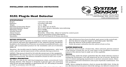
INSTALLATION AND MAINTENANCE INSTRUCTIONS Plug in Rate of Rise Detector with Temperature Alarm Temperatures Humidity Range Alarm Voltage Current 4.1 inches 104 mm 2.1 inches 53 mm 5 ounces 150 g 32 to 100 0 to 38 10 to 93 Relative Humidity Reset by momentary power interruption 135 57 Fixed or 15 rate of rise 15 35 VDC 100 Ohio Avenue St Charles Illinois 60174 FAX 630 377 6495 INSTALLINg detector must be installed in compliance with the control panel installa manual and meet the requirements of the authority having jurisdiction In the National Fire Protection Association has published codes stan and recommended practices for the installation and use of detectors 72 the installer must be familiar with these requirements with local and any special requirements of the authority having jurisdiction This manual should be left with the owner user of this equipment This detector must be tested and maintained regularly following 72 requirements The detector should be cleaned at least once a year DESCRIPTION 5451 is a rate of rise with fixed temperature alarm thermal detector a state of the art dual thermistor sensing circuit These detectors are to provide open area protection with 50 foot spacing capability and to be used with compatible control panels only LEDs on each detector light to provide 360 visibility of the detector in Remote LED annunciator capability is provided as standard and the remote LED annunciator is available as an optional accessory SELECTION AND WIRINg gUIDE to the installation instructions for the plug in detector bases for base selec and wiring instructions System Sensor has available a variety of detector for these heat detectors including 2 wire applications with and without and or current limiting resistors for use with control panels that require This detector is only to be used with 400 and 400B series bases the System Sensor plug in base to be used with the detector following instructions in the base manual All wiring must conform to applicable installation codes and regulations Verify that all detector bases are installed that the initiating device have been tested and that the wiring is correct Refer to detector base for testing procedure the power from initiating device circuits before installing detectors Detectors Insert the detector into the detector base Turn the detector clockwise until the detector drops into place Continue turning detector clockwise to lock it in place After all detectors have been installed apply power to the control unit Test the detector using the magnet as described under TESTING Reset the detector at the system control panel Notify the proper authorities that the system is in operation RESISTANCE detector bases include a feature that when activated prevents removal the detector without the use of a tool Refer to the installation instruction of the detector base to make use of this capability testing notify the proper authorities that the heat detector system is maintenance and therefore the system will temporarily be out service Disable the zone or system undergoing maintenance to prevent alarms must be tested after installation and periodic maintenance The 5451 be tested as follows Test Magnet System Sensor Model No M02 04 Position the magnet against the cover opposite the test module See Figure 1 The LEDs on the detector should light within 10 seconds If the LEDs to light check the power to the detector and the wiring in the base Reset the detector at the system control panel Test Module System Sensor Model No MOD400 or MOD400R The MOD400 or MOD400R is used with a DMM or volt meter to the detector sensitivity as described in the module manual Direct Heat Method Hair dryer of 1000 1500 watts From the side of the detector direct the heat toward the sensor Hold heat source about 15 cm away to prevent damage to the cover testing If a detector goes into alarm it will reset only if the detector has cooled if its power is momentarily interrupted Check the control panel being to determine whether the RESET switch or some other auxiliary device control momentarily cuts off power to the detector loop that fail these tests should be cleaned as described under MAIN and retested If the detectors still fail these tests they should be for repair 5451 detector has been designed to be as maintenance free as possible air borne dust however can accumulate on the detector sensing and cause them to become less sensitive All detectors should be and cleaned at least once a year and those in dustier areas should be and cleaned more often Detectors must also be cleaned and tested im after a fire cleaning notify the proper authorities that the system is undergoing and therefore the system will temporarily be out of service the loop or system undergoing maintenance to prevent unwanted Remove detector from mounting base Use a vacuum cleaner to remove dust from the sensing chamber Reinstall the detector Test detector as described under TESTING 1 BOTTOM AND SIDE VIEWS ShOWINg POSITION OF TEST MAgNET MODULE refer to insert for the Limitations of Fire Alarm Systems LIMITED WARRANTY Sensor warrants its enclosed heat detector to be free from defects in materials workmanship under normal use and service for a period of three years from date of System Sensor makes no other express warranty for this heat detector No representative dealer or employee of the Company has the authority to increase alter the obligations or limitations of this Warranty The Company obligation of this shall be limited to the repair or replacement of any part of the heat detector is found to be defective in materials or workmanship under normal use and ser during the three year period commencing with the date of manufacture After phon System Sensor toll free number 800 SENSOR2 736 7672 for a Return Authorization send defective units postage prepaid to System Sensor Repair Department RA 3825 Ohio Avenue St Charles IL 60174 Please include a note describing malfunction and suspected cause of failure The Company shall not be obligated to or replace units which are found to be defective because of damage unreasonable modifications or alterations occurring after the date of manufacture In no case shall Company be liable for any consequential or incidental damages for breach of this any other Warranty expressed or implied whatsoever even if the loss or damage is by the Company negligence or fault Some states do not allow the exclusion or of incidental or consequential damages so the above limitation or exclusion not apply to you This Warranty gives you specific legal rights and you may also other rights which vary from state to state System Sensor