System Sensor 7251 Product Manual
File Preview
Click below to download for free
Click below to download for free
File Data
| Name | system-sensor-7251-product-manual-2650349817.pdf |
|---|---|
| Type | |
| Size | 1.42 MB |
| Downloads |
Text Preview
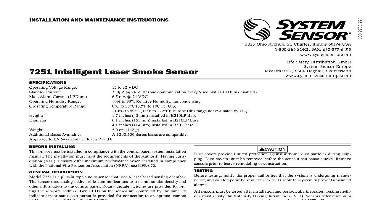
INSTALLATION AND MAINTENANCE INSTRUCTIONS 3825 Ohio Avenue St Charles Illinois 60174 USA FAX 630 377 6495 Safety Distribution GmbH Sensor Europe 2 8604 Hegnau Switzerland Intelligent Laser Smoke Sensor Voltage Range Current Alarm Current LED on Humidity Range Temperature Range Bases Available to EN 54 7 at alarm levels 7 and 8 to 32 VDC 24 VDC one communication every 5 sec with LED blink enabled mA 24 VDC to 93 Relative Humidity noncondensing to 38 32 to 100 U S to 50 14 to 122 Europe this range not evaluated by UL inches 43 mm installed in B210LP Base inches 155 mm installed in B210LP Base inches 104 mm installed in B501 Base oz 142 g 200 500 Series bases are compatible INSTALLING sensor must be installed in compliance with the control panel system installation The installation must meet the requirements of the Authority Having Juris AHJ Sensors offer maximum performance when installed in compliance the National Fire Protection Association NFPA see NFPA 72 DESCRIPTION 7251 is a plug in type smoke sensor that uses a laser based sensing chamber sensor uses analog addressable communications to transmit smoke density and information to the control panel Rotary decade switches are provided for set the sensor address Two LEDs on the sensor are controlled by the panel to sensor status An output is provided for connection to an optional remote annunciator P N RA400Z RA100Z detector requires compatible addressable communications to function properly this sensor to listed compatible control panels only Sensor recommends spacing sensors in compliance with NFPA 72 In low flow applications with smooth ceilings space sensors 30 feet apart For specific regarding sensor spacing placement and special applications refer to 72 or the System Smoke Detector Application Guide available from System INSTRUCTIONS wiring must be installed in compliance with the National Electrical Code appli local codes and any special requirements of the Authority Having Jurisdiction wire gauges should be used The installation wires should be color coded to wiring mistakes and ease system troubleshooting Improper connections will a system from responding properly in the event of a fire power from the communication line before installing sensors wiring must conform to applicable local codes ordinances and regulations Wire the sensor base supplied separately per the wiring diagram see Figure 1 the desired address on the sensor address switches see Figure 2 Install the sensor into the sensor base Push the sensor into the base while turning it to secure it in place After all sensors have been installed apply power to the control unit and acti the communication line the sensor s as described in the TESTING section of this manual covers provide limited protection against airborne dust particles during ship Dust covers must be removed before the sensors can sense smoke Remove prior to heavy remodeling or construction testing notify the proper authorities that the system is undergoing mainte and will temporarily be out of service Disable the system to prevent unwanted sensors must be tested after installation and periodically thereafter Testing meth must satisfy the Authority Having Jurisdiction AHJ Sensors offer maximum when tested and maintained in compliance with NFPA 72 sensor can be tested in the following ways Functional Magnet Test P N M02 04 01 or M02 09 00 This sensor can be functionally tested with a test magnet The test magnet simulates smoke in the sensing chamber testing the sensor and connections to the control panel Hold the test magnet in the magnet test area as shown in Figure 3 The sensor should alarm the panel Two LEDs on the sensor are controlled by the panel to indicate sensor Coded signals transmitted from the panel can cause the LEDs to latch on or latch off Refer to the control panel technical documen for sensor LED status operation and expected delay to alarm Smoke Entry Aerosol Generator Gemini 501 The GEMINI model 501 aerosol generator can be used for smoke entry Set the generator to represent 4 ft to 5 ft obstruction as de in the GEMINI 501 manual Using the bowl shaped applicator aerosol until the panel alarms sensor that fails any of these tests should be cleaned as described under CLEAN and retested If the sensor fials after cleaning it must be replaced and returned repair testing is complete restore the system to normal operation and notify the authorities that the system is back in operation 1 WIRING DIAGRAM not loop wire under terminal 1 or 2 Break wire run to provide of connection A OPTIONAL WIRING is recommended that the detector be removed from its mounting base to facilitate The detector is cleaned as follows Before removing the detector notify the proper authorities that the smoke system is undergoing maintenance and will be temporarily out of service the zone or system undergoing maintenance to prevent unwanted alarms Remove the detector cover by prying away the four side tabs with a small screwdriver and then pulling the cover from the base Vacuum the screen carefully without removing it If further cleaning is required with Step 3 otherwise skip to Step 7 Remove the screen chamber cover assembly by pulling it straight out see Fig 4 Clean the chamber by vacuuming or blowing out dust and particles Replace the sensing chamber cover aligning the arrow on the top with arrow on printed circuit board To replace the screen place it over the chamber assembly turning it until it into place Replace the cover using the LEDs to align the cover and then gently pushing it it locks into place the detector as described in TESTING Reinstall the detector Reconnect disabled circuits Notify the proper authorities that the system is back on line SAFETY INFORMATION smoke detector does not produce any hazardous laser radiation and is certified a Class 1 laser product under the U S Department of Health and Human Services Radiation Performance Standard according to the Radiation Control for and Safety Act of 1968 radiation emitted inside the smoke detector is completely within the protective and external covers The laser beam cannot escape from the detector during phase of operation Center of Devices and Radiological Health CDRH of the U S Food and Drug implemented regulations for laser products on August 2 1976 These apply to laser products manufactured after August 1 1976 Compliance is for products marketed in the United States of controls adjustments or performance of procedures other than those specified this manual may result in hazardous radiation exposure NOTE REGARDING SMOKE DETECTOR GUARDS detectors are not to be used with detector guards unless the combination has evaluated and found suitable for that purpose 2 ROTARY DECADE ADDRESS SWITCHES 4 SENSOR ASSEMBLY 0 0 COVER REMOVAL TABS ASSEMBLY 3 TEST MAGNET POSITION TEST STATUS 0832 CPD 0192 de Juarez S de R L de C V Rosa Maria Y Fuentes No 7070 C P Parque Industrial Fuentes Juarez Chihuahua MEXICO refer to insert for the Limitations of Fire Alarm Systems LIMITED WARRANTY Sensor warrants its enclosed smoke detector to be free from defects in materials workmanship under normal use and service for a period of three years from date manufacture System Sensor makes no other express warranty for this smoke detec No agent representative dealer or employee of the Company has the authority to or alter the obligations or limitations of this Warranty The Company