System Sensor accuflow-lfd Install and Maint Instructions

File Preview
Click below to download for free
Click below to download for free
File Data
| Name | system-sensor-accuflow-lfd-install-and-maint-instructions-3607185429.pdf |
|---|---|
| Type | |
| Size | 675.96 KB |
| Downloads |
Text Preview
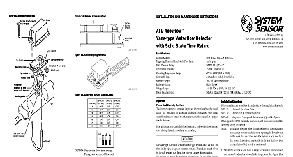
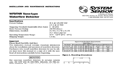
INSTALLATION AND MAINTENANCE INSTRUCTIONS Accuflow Low Flow Waterflow Detector Solid State Time Retard Ratings Threshold Bandwidth Flow Rate Pressure Rating Installed Temperature Range Pipe Weight Rating Range Requirements S Patent Number A 125VAC 2 A 30VDC gpm maximum PSI Max x 3.0 W x 6.7 D F to 120 0 C to 49 C Low Flow models listed below to 7 lb according to size Type 4 V DC 108 VAC at 12 and 24 V DC or at 120 VAC 3,845,259 Read Carefully And Save instruction manual contains important information about the instal and operation of waterflow detectors Purchasers who install detectors for use by others must leave this manual or a copy of with the user all instructions carefully before beginning Follow only those instruc that apply to the model you are installing vane type waterflow detectors in wet pipe systems only Do NOT use in dry pipe deluge or preaction systems The sudden inrush of wa in such systems may break the vane or damage the mechanism not use in potentially explosive atmospheres Do not allow unused to remain exposed Of Operation waterflow detectors mount to water filled pipes in sprinkler sys Waterflow in the pipe deflects a vane which produces a switched after a specified delay All waterflow detectors have a con delay mechanism Delays do NOT accumulate they reset if the of water stops before the entire delay has elapsed All switches actu when the water flow rate is 3 gallons per minute or greater This Sys Sensor installation manual covers the following waterflow detectors sprinkler fire alarm applications Flow Models Pipe O D Nominal Wall Thickness 60.3mm 73.0mm 76.0mm 88.9mm 114.3mm to 4.5mm to 5.2mm to 4.7mm to 5.6mm to 6.4mm LFD models are approved for use on stainless steel and brass pipe NOT use any of the LFD models on any other pipe materials NOT install steel or iron pipe sections in copper piping for mounting a detector Incompatibility between the dissimilar metals causes corrosion SENSOR Division of Pittway 3825 Ohio Avenue St Charles Illinois 60174 FAX 630 377 6495 Compatibility LFD waterflow indicators may receive power and operate on a two initiating zone of a fire alarm control panel When determining com of these devices the standby operating voltage of the control must be between 8.5 and 35 volts In the standby mode the LFD a maximum current of 0.3mA In alarm the LFD acts as a short the initiating zone similar to a manual fire box For two wire con fire alarm control panels not more than 5 waterflow indica may be connected to a single initiating zone The maximum retard time of the waterflow indicator plus the initiating zone shall not ex 90 seconds two wire addressable control panels the number of waterflow indi connected to the panel signaling line circuit shall be limited by the circuit current capacity Fire Alarm Code of Sprinkler Systems Testing and Maintenance of Sprinkler Systems Guidelines installing any waterflow alarm device be thoroughly familiar with 72 13 25 750 Water Mist Fire Protection Systems applicable NFPA standards local codes and the requirements of the having jurisdiction methods other than those listed in this installation may prevent the device from reporting the flow of water the event the associated sprinkler system is activated by a System Sensor is not responsible for devices that have been installed tested or maintained Mount the detector where there is adequate clearance for installation removal and a clear view of it for inspections See Figure 1 for dimensions Locate detector 6 to 7 ft above the floor to protect from potential damage On horizontal runs position the detector on the top or side of the pipe not mount it upside down because condensation may collect in the and impair the operation of the detector For vertical flow ap mount the detector on pipe through which water flows up Otherwise the unit may not operate properly Mount the detector at least 6 inches from a fitting that changes the di of water flow and no less than 24 inches from a valve or drain Be sure the direction of flow arrow matches the direction of flow the pipe Instructions Drain the pipe Cut a hole at the desired location Center the hole in the pipe as in Figure 2 and be sure the hole is perpendicular to the center the pipe Before drilling use a punch or scribe to mark the drill site prevent the bit from slipping If the hole is off center the vane will against the inside wall of the pipe Use a drill or hole saw to cut a of the proper diameter See Table 1 for hole size drilling the hole with a hole saw make certain that the center of the does not remain in the pipe Remove burrs and sharp edges from the hole Clean and remove scale and foreign matter from the inside of the pipe for one di on each side of the hole to ensure free movement of the Clean the outside of the pipe to remove dirt metal chips cutting lubricant Manuals Online Seat the gasket against the saddle and mount the detector directly to pipe Carefully roll the vane opposite the direction of flow and in it through the hole Seat the saddle firmly against the pipe so that locating boss goes into the hole the U bolt tightening the nuts alternately to ensure a uniform See Table 2 for torque values Remove the metal cover with the tamper proof wrench provided Move actuator lever back and forth to check for binding If the vane remove the detector and correct the cause before proceeding the sprinkler system and check for leaks around the waterflow detec If it leaks first check for the proper torque on the U bolt nuts If the persists drain the system and remove the detector refer to Mainte Check for dirt or foreign objects under the gasket and make sure the pipe surface is not dented Reinstall the detector and check again leaks Do not proceed until all leaks have been stopped sure the direction of flow arrow points in the right direction or else flow will go unreported See Figure 9 Voltage Electrocution Hazard Do not handle live AC wiring or work on a to which AC power is applied Doing so may result in injury or death All models have two wires and two sets of terminals Wires W1 W2 designated on PCB These wires are con to a latching normally open as in No Flow relay contact They isolated from all electronics They will close and cause a short when flows and the retard time elapses They will remain shorted until stops Once waterflow stops these contacts will re open Terminals T2 designated on PCB This is a two screw terminal The Accuflow gets its power from these terminals These termi must have voltage present from the FACP or other suitable source of before anything will work If no power is present the Accuflow not provide proper alarm signals These terminals will accept power any polarity as well as AC line power Relay Terminals T1 designated on PCB This is a THREE screw block These terminals are connected to a latching Form C re In no flow conditions COM is connected to A When flow is de COM will disconnect from A and connect to B This relay will in that state and reset after water stops flowing Adjust Dip Switch to desired time delay See Figure 11 For Dip Switch see Figure 9 When connected to a listed sprinkler fire alarm control panel the initi circuit must be nonsilenceable A ground screw is provided with all waterflow detectors When is required clamp wire with screw in hole located between entrance holes See Figure 10A page 4 a second conduit entry is required remove the knockout plug using flat blade screwdriver as shown on Figure 10B page 4 Strike sharply a hammer to pierce the wall of the knockout plug Move to an wall section and repeat until the plug falls out Make sure that waterflow detector is supported adequately during this operation avoid injury terminals