System Sensor APA151 Manual

File Preview
Click below to download for free
Click below to download for free
File Data
| Name | system-sensor-apa151-manual-4789302165.pdf |
|---|---|
| Type | |
| Size | 1.17 MB |
| Downloads |
Text Preview
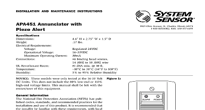
INSTALLATION AND MAINTENANCE INSTRUCTIONS Annunciator Piezo Alert Requirements Voltage Operating Current Reverberant Room Operating Temperature Range L 2.9 W 45 D lbs 24VDC VDC binding head screws 12 AWG to 18 AWG wire dBA min 10 ft to 49 32 to 120 to 93 non condensing 3825 Ohio Avenue St Charles Illinois 60174 FAX 630 377 6495 These models were only tested at the 16 33 Volt DC limits This does include the 80 low end or 110 high end voltage limits This manual be left with the owner user of this equipment INFORMATION National Fire Protection Association NFPA has published codes stan and recommended practices for the installation and use of this product is recommended that the installer be familiar with these requirements with codes and any special requirements of the local authority having juris For further information consult NFPA 72 and 90A requirements System Sensor APA151 annunciator with piezo alert is an audible signal for fire alarm service It is intended for use in System Sensor 4 wire duct smoke detector applications without a system control panel comply with NFPA 90A APA151 provides a red alarm LED with an audible annunciation of an signal and a green power LED 1 the APA151 as shown in Figure 1 thru Figure 3 depending on what duct detector is being utilized Limit wire runs to 25 ohms or less per inter wire the APA151 to the single gang box using the two screws provided or to the wall or ceiling TEST the wiring diagrams below to insure proper wiring to the APA151 power to the duct smoke detector Visually check the supervisory LED to make sure it is operational the detector into alarm state The alarm LED red will light and the piezo will sound Reset the detector 2 WIRING DIAGRAM FOR D4120 TO APA151 LED ALARM TEST RESET OUT OUT NO C LED POWER WIRING DIAGRAM SHOWN IS FOR D4120 4 WIRE DUCT SMOKE SYSTEM EQUIPPED WITHOUT A CONTROL PANEL A TROUBLE CONDITION IS INDICATED LOSS OF GREEN LED 3 WIRING DIAGRAM FOR D4120 DH100ACDC TO APA151 Wiring to APA151 Signal Power N O COM Power LED LED CONTENTS APA151 annunciator with piezo alert screw pack containing two mounting screws Wiring diagram shown is for DH100ACDC 4 wire duct detector system equipped without a control panel LIMITATIONS OF SOUNDERS sounder will not operate if the power is cut off for any reason sounder may not be heard The loudness of the sounder meets or exceeds the current However the sounder may not alert a sound sleeper or one who has recently drugs or has been drinking alcoholic beverages This sounder may not be heard if is placed in an area that is separated by a closed door or if it is located on a different from the person in a hazardous situation or if it is placed too far away to be heard ambient noise such as traffic air conditioners machinery or musical appliances may prevent alert persons from hearing the alarm sounder may not be heard by persons who are hearing impaired In this case a indicator shall also be used these reasons Pittway recommends that sounders 85dBA minimum at 10 feet in a residence shall be placed on every level and in every bedroom that does not a smoke detector with a built in sounder LIMITED WARRANTY Sensor warrants its enclosed product to be free from defects in materials and under normal use and service for a period of three years from date of System Sensor makes no other express warranty for the enclosed product agent representative dealer or employee of the Company has the authority to in or alter the obligations or limitations of this Warranty The Company obligation this Warranty shall be limited to the replacement of any part of the product which is to be defective in materials or workmanship under normal use and service during three year period commencing with the date of manufacture After phoning System toll free number 800 SENSOR2 736 7672 for a Return Authorization number defective units postage prepaid to Honeywell 12220 Rojas Drive Suite 700 El Paso 79936 USA Please include a note describing the malfunction and suspected cause failure The Company shall not be obligated to replace units which are found to be because of damage unreasonable use modifications or alterations occurring the date of manufacture In no case shall the Company be liable for any consequen or incidental damages for breach of this or any other Warranty expressed or implied even if the loss or damage is caused by the Company negligence or fault states do not allow the exclusion or limitation of incidental or consequential dam so the above limitation or exclusion may not apply to you This Warranty gives you legal rights and you may also have other rights which vary from state to state System Sensor 06 10