System Sensor b224bi Install and Maint Instructions

File Preview
Click below to download for free
Click below to download for free
File Data
| Name | system-sensor-b224bi-install-and-maint-instructions-0678419352.pdf |
|---|---|
| Type | |
| Size | 699.79 KB |
| Downloads |
Text Preview
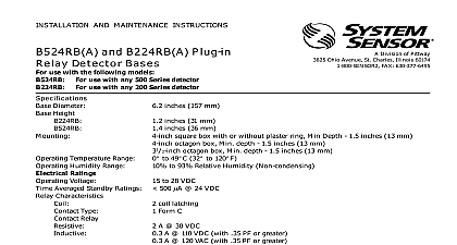
INSTALLATION AND MAINTENANCE INSTRUCTIONS and B224BI Plug in Isolator Bases use with the following smoke detectors US 2551 2551T 5551 5551R 2251 3251 SENSOR Division of Pittway 3825 Ohio Avenue St Charles Illinois 60174 FAX 630 377 6495 Diameter Height B224BI B524BI Temperature Range Humidity Range Ratings Voltage Standard Alarm to 28 VDC Maximum Maximum inches 157 mm inches 31 mm inches 36 mm square box with or without plaster ring Min depth 1.5 inches 13 mm octagon box Min depth 1.5 inches 13 mm octagon box Min depth 1.5 inches 13 mm C to 60 cid 176 C 14 cid 176 F to 140 cid 176 F Do not install in locations where normal ambient temperature extends beyond 0 cid 176 to 49 cid 176 C 32 cid 176 to 120 cid 176 F to 93 Relative Humidity Non condensing Installing thoroughly read the system wiring and installation and manual I56 407 Guide for Proper Use of Sys Smoke Detectors which provides detailed information detector spacing placement zoning and special appli Copies of these manuals are available at no charge System Sensor This manual should be left with the owner user this equipment The detectors used with these bases must be and maintained following NFPA 72 requirements detectors used with these bases should be cleaned at once a year Information bases prevent an entire communications loop from disabled when a short circuit occurs They accom this by isolating that part of the loop containing the from the remainder of the circuit These bases also restore the entire loop when the cause of the circuit is corrected In general up to 25 addressable may be isolated between isolator bases For the of determining the number of devices between bases one 3251 is equivalent to 12 addressable de For example 13 2251 and 1 3251 may be between two isolator bases detector base mounts directly to 31 2 and 4 inch octa and 4 inch square boxes with or without a plaster To mount remove the decorative ring by rotating it in direction to unhook the snaps Then separate the from the base Install the base on the box using the supplied with the junction box and the appropriate in the base Replace the decorative ring on the base rotate it in either direction until the ring snaps in place Figure 1 Manuals Online Guidelines wiring must be installed in compliance with all appli local codes and any special requirements of the local having jurisdiction using the proper wire sizes conductors used to connect smoke detectors to control and accessory devices should be color coded to re the likelihood of wiring errors Improper connections prevent a system from responding properly in the event a fire signal wiring the wiring between interconnected de it is recommended that the wire be no smaller 18 gauge 1.0 square mm However wire sizes up to gauge 3.3 square mm can be used with the base The of twisted pair wiring or shielded cable for the power and loop is recommended to minimize the effects of interference Detector head power is supplied by terminals 1 2 Therefore the head will be part of this group shielded cable is used the shield connection to and from detector must be continuous by using wire nuts crimp or soldering as appropriate for a reliable connection system control panels have specifications for allow loop resistance Consult the control panel specifica for the total loop resistance allowed before wiring the loops the zone wiring of all bases in the system before in detectors This includes checking the wiring for correct polarity ground fault testing and per a dielectric test 2 PAIR RECOMMENDED 1 Mounting base to electrical box ON NOT NOT INTELLIGENT COMM COMM COMM COMM Manuals Online A OPTIONAL WIRING 3 Wiring diagram COMPATIBLE PANEL LINE PAIR RECOMMENDED WIRING SHOWN IS SUPERVISED OF ADDRESSABLE DEVICES ARE SEPARATED BY FAULT ISOLATOR ANY COMBINATION OF COMPATIBLE DEVICES MAY BE MIXED WITHIN A GROUP PAIR OF FAULT ISOLATOR BASES WILL DISCONNECT A OF DEVICES IF A SHORT CIRCUIT OCCURS ON THE LINE CIRCUIT WITHIN THAT GROUP c x c x V I Instructions wiring connections by stripping about 3 8 10 mm insulation from the wire end Then insert the wire into appropriate terminal and tighten the screw Wire the line in to terminal 1 Insert both com line in and communication line out to ter 2 Wire communication line out to terminal 3 Figures 2 and 3 4 is for shielded cable only see Figures 2 and 3 shielded cable is used the shield connection to and from detector must be continuous by using wire nuts crimp or soldering to ensure a reliable connection If shielded is NOT used leave terminal 4 in the screwed down label is affixed to the base for recording the zone ad and type of detector being installed at the base loca This information is useful for setting the detector head and for verification of the sensor type required for location all detector bases have been wired and mounted and loop wiring has been checked the detector heads may installed in the bases Feature Do not use the tamper resist feature if the removal is to be used detector base includes a tamper resist feature that pre its removal from the base without the use of a tool activate this feature break the tab from the detector as shown in Figure 4A see Page 4 Then install the remove the detector from the base once the tamper re feature has been activated insert a small bladed screw into the slot in the side of the base and push the lever away from the detector head see Figure 4B 4 This allows the detector to be rotated counter for removal Head removal after the tamper resist feature has activated requires removal of the decorative tamper resist feature can be defeated by breaking and the plastic lever from the base However this pre the feature from being used again Manuals Online 4A Activating the tamper resist feature 4B Removing the detector head from the LEVER TAB AT LINE BY TOWARD OF BASE SMALL BLADED TO PLASTIC LEVER DIRECTION OF Limitations of Property Protection Smoke Detectors