System Sensor B401BR Manual

File Preview
Click below to download for free
Click below to download for free
File Data
| Name | system-sensor-b401br-manual-8971256403.pdf |
|---|---|
| Type | |
| Size | 778.46 KB |
| Downloads |
Text Preview
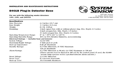
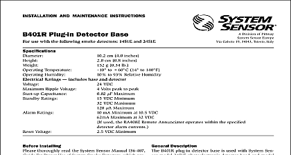
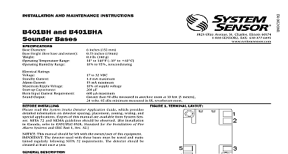
inSTaLLaTiOn and mainTenanCe inSTrUCTiOnS Plug in detector Base use with the following detectors 1451 2451 and 2451TH 3825 Ohio Avenue St Charles Illinois 60174 FAX 630 377 6495 inches 157 mm typical inches 29 mm typical lb 130 g typical inch square box with or without plaster ring Min Depth 1.5 inches inch octagon box Min Depth 1.5 inches inch octagon box Min Depth 1.5 inches to 60 14 to 140 Do not install where normal ambient temperature extends beyond 0 to 49 32 to 120 to 93 Relative Humidity Diameter Height Temperature Range Humidity Range Ratings includes base and detector VDC Voltage Volts peak to peak Ripple Voltage Maximum Capacitance VDC Minimum Ratings VDC Maximum Maximum mA Minimum at 10.5 VDC Ratings mA Maximum at 32 VDC optional RA400Z RA100Z Remote Annunciator operates within the specified detector alarm currents Voltage VDC Minimum Sec Maximum Time Time Sec Maximum inSTaLLing thoroughly read the System Sensor manual I56 407 Guide for Proper of System Smoke Detectors which provides detailed information on de spacing placement zoning wiring and special applications Copies of manual are available at no charge from System Sensor For installations Canada refer to CAN4 S524 Standard for the Installation of Fire Alarm and CEC Part 1 Sec 32 This manual should be left with the owner user of this equipment The detector used with this base must be tested and maintained following NFPA 72 requirements The detector used with this base be cleaned at least once a year deSCriPTiOn plug in detector base B401BR is used with System Sensor 400 Series ionization and heat detector heads The ability to accept variety of detector heads makes this base more versatile than equivalent models Refer to the System Sensor catalog for other available detector bases B401BR base is intended for use in 2 wire systems with screw terminals for power ground and remote annunciator connections The B401BR also contains a resistor to provide current limiting in the alarm state detector base mounts directly to 31 inch and 4 inch octagon boxes and inch square boxes with or without plaster rings To mount remove decora ring by turning it in either direction to unhook the snaps then separate ring from the base the base to the box using the screws supplied with the junction box and appropriate mounting slots in the base Place decorative ring onto base turn in either direction until the ring snaps in place see Figure 1 gUideLineS figUre 2 wiring must be installed in compliance with the National Electrical Code the local codes having jurisdiction Proper wire gauges should be used conductors used to connect smoke detectors to control panels and acces devices should be color coded to prevent wiring mistakes Improper con can prevent a system from responding properly in the event of a fire signal wiring the wiring between interconnected detectors it is recom that the wire be no smaller than 18 gauge 1.0 square mm Wire up to 12 gauge wire 2.5 square mm may be used with the base For system performance the power and loop wires should be twisted and installed in separate grounded conduit to protect the loop from elec interference detectors and alarm system control panels have specifications for al loop resistance Consult the control panel manufacturer specifica for the total loop resistance allowed for the particular model control being used before wiring the detector loops system supervision For terminals 2 3 and 5 do not use looped wire un terminals Break wire run to provide system supervision of connections connections are made by simply stripping insulation from the end of the sliding the bare end of the wire under the clamping plate and tightening clamping plate screw Use the strip gauge molded into the base for ease of to terminals Sensor smoke detectors and mounting bases are marked with a com identifier located as the last digit of a five digit code stamped on the of the product Connect detectors mounting bases only to compatible units as indicated in System Sensor compatibility chart which con a current list of UL listed control units and detector head base combina A copy of this list is available from System Sensor upon request zone wiring of the detector base should be checked before the detector are installed in them To make this possible this base contains a spe spring type shorting jumper After a detector base is properly wired and on an electrical box make sure that the jumper spring is in contact the base of Terminal 3 This temporary connection shorts the negative in negative out leads and permits the wiring of the loop to be checked for all the detector bases have been wired and mounted and the loop wir has been checked the detector heads may be installed in the bases The spring in the base will disengage when the detector head is turned place feaTUre not use the tamper resist feature if the XR5 removal tool is to be used detector base also includes an optional tamper resist feature that when prevents removal of the detector without the use of a tool activate this feature break the tab from the detector base as shown in 3A and install the detector To remove the detector from the base once tamper resist feature has been activated insert a small bladed screwdriver the slot in the side of the base and press the plastic lever away from the head see Figure 3B This allows the detector to be rotated counter and removed requires removal of the decorative ring removal after the tamper resist feature has been activated tamper resist feature can be defeated by breaking and removing the plas lever from the base However this permanently defeats the tamper resist 1 mOUnTing deTeCTOr TO BOx ON SUPPLIED SUPPLIED 2 TYPiCaL Wiring diagram fOr 2 Wire deTeCTOr SYSTemS For system supervision Do not loop wire under terminals 2 3 and 5 Break wire run to ensure system supervision of connections FAULT TOLERANT WIRING 3a aCTivaTing TamPerPrOOf feaTUre 3B remOving deTeCTOr head frOm BaSe LEVER SMALL BLADED SCREWDRIVER TO PUSH LEVER IN DIRECTION OF ARROW TAB AT DOTTED LINE BY TOWARD CENTER OF BASE refer to insert for the Limitations of Fire Alarm Systems LimiTed WarranTY Sensor warrants its enclosed smoke detector base to be free from defects in ma and workmanship under normal use and service for a period of three years from of manufacture System Sensor makes no other express warranty for this smoke base No agent representative dealer or employee of the Company has the au to increase or alter the obligations or limitations of this Warranty The Company of this Warranty shall be limited to the repair or replacement of any part of the detector base which is found to be defective in materials or workmanship under use and service during the three year period commencing with the date of manu After phoning System Sensor toll free number 800 SENSOR2 736 7672 for a Authorization number send defective units postage prepaid to System Sensor Department RA 3825 Ohio Avenue St Charles IL 60174 Please a note describing the malfunction and suspected cause of failure The Company not be obligated to repair or replace units which are found to be defective because damage unreasonable use modifications or alterations occurring after the date of In no case shall the Company be liable for any consequential or incidental for breach of this or any other Warranty expressed or implied whatsoever even the loss or damage is caused by the Company neg