System Sensor B401R Manual

File Preview
Click below to download for free
Click below to download for free
File Data
| Name | system-sensor-b401r-manual-6935408217.pdf |
|---|---|
| Type | |
| Size | 746.82 KB |
| Downloads |
Text Preview
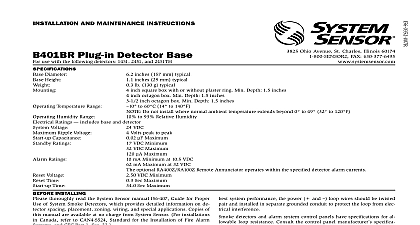
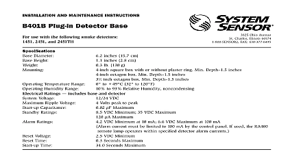
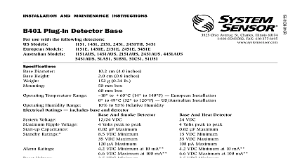
A Division of Pittway System Sensor Europe Caboto 19 34143 Trieste Italy AND MAINTENANCE INSTRUCTIONS Plug in Detector Base use with the following smoke detectors 1451E and 2451E Temperature Humidity Ratings includes base and detector Ripple Voltage Capacitance Ratings cm 4.0 inches cm 0.8 inches g 0.34 lb to 60 cid 176 C 14 cid 176 to 140 cid 176 F to 93 Relative Humidity VDC Volts peak to peak m F Maximum VDC Minimum VDC Maximum m A Maximum mA Minimum at 10.5 VDC Maximum at 32 VDC used the RA400Z Remote Annunciator operates within the specified alarm currents VDC Minimum Ratings Voltage Installing thoroughly read the System Sensor Manual I56 407 For Proper Use of System Smoke Detectors which pro detailed information on detector spacing placement wiring and special applications Copies of this are available at no charge from System Sensor This manual should be left with the owner user this equipment The detector used with this base must be and maintained regularly following NFPA 72 require The detector used with this base should be cleaned least once a year Description B401R plug in detector base is used with System Sen model 2451E photoelectronic detector head and model ionization detector head The capability of plugging detectors into a variety of special bases makes them versatile than equivalent direct wired models Refer the System Sensor catalog for other plug in detector B401R base is intended for use in 2 wire systems with terminals provided for power ground and remote connections The B401R base also contains a to provide current limiting in the alarm state Terminals ANNUNCIATOR V IN REMOTE ANNUNCIATOR V OUT USED V IN AND V OUT remote annunciator is not used polarity to these may be reversed detector bases mount to typical junction boxes In the base to the box using the screws supplied with the box Figure 2 shows mechanical mounting details Installation Guidelines wiring must be installed in compliance with the Na Electrical Code and the local codes having jurisdic Proper wire gauges should be used The conductors to connect smoke detectors to control panels and ac devices should be color coded to prevent wiring Improper connections can prevent a system from properly in the event of a fire signal wiring the wiring between interconnected de or from detectors to auxiliary devices it is recom that single conductor wire be no smaller than and that two or three conductor wire be no than 1.0mm2 For best system performance alarm conductors should be installed in separate grounded or shielded cable to protect the alarm loop from ex electrical interference detectors and alarm system control panels have for allowable loop resistance Consult the panel manufacturer specifications for the total resistance allowed for the particular model control being used before wiring the detector loops Instructions connections are made by stripping about 1 cm 3 8 insulation from the end of the wire use strip gauge in base sliding the bare end of the wire under the plate and tightening the clamping plate screw zone wiring of the detector bases should be checked the detector heads are installed To make this this base contains a special spring type shorting shown in Figure 2 After a detector base is wired and mounted to an electrical box make that the shorting spring is in contact with terminal 3 1 Terminal layout 2 Mounting base to box 3 Typical wiring diagram for 2 wire detector system IF REMOTE ANNUNCIATOR cid 13 NOT USED POLARITY TO cid 13 TERMINALS MAY BE cid 13 A OPTIONAL WIRING not loop wire under terminals Break wire run to provide supervision of connections temporary connection permits the wiring of the loop be checked for continuity before installation of the heads shorting spring in the base will automatically when the detector head is removed from the DO NOT remove the shorting spring since it as the detector head is turned into the base the circuit all the detector bases have been wired and mounted the loop wiring has been checked the detector heads be installed in the bases Feature detector base also includes an optional tamper resis feature that when activated prevents removal of the without the use of a tool activate this feature break off the tab on the detector see Figure 4 then install the detector To remove the from the base after the tamper resistance feature been activated place a small standard screwdriver into small hole on the side of the base and push the plastic away from the detector head see Figure 5 This will the detector to be rotated counterclockwise for tamper resistance feature may be defeated by breaking removing the plastic lever from the base however this ever using the feature again Remote Annunciator Units model RA400Z Remote Annunciator LED is available an optional accessory This unit has a rectangular plate fits U S single gang light switch boxes If a different of remote annunciator is used it must use less than at 3.0 V 4 Activating tamper resistance feature 5 Removing detector head from base LEVER TAB AT cid 13 LINE BY cid 13 TOWARD cid 13 OF BASE SMALL BLADED cid 13 TO cid 13 PLASTIC LEVER cid 13 DIRECTION OF cid 13 Limitations of Property Protection Smoke Detectors smoke detector used with this base is designed to activate and ini emergency action but will do so only when it is used in conjunction an authorized fire alarm system This detector must be installed in with NFPA standard 72 detectors will not work without power AC or DC powered detectors will not work if the power supply is cut off detectors will not sense fires which start where smoke does not the detectors Smoldering fires typically do not generate a lot of which is needed to drive the smoke up to the ceiling where the detector is usually located For this reason there may be large de in detecting a smoldering fire with either an ionization type detector a photoelectric type detector Either one of them may alarm only after has initiated which will generate the heat needed to drive the to the ceiling from fires in chimneys in walls on roofs or on the other side of a door s may not reach the smoke detector and alarm it A detector detect a fire developing on another level of a building quickly or at For these reasons detectors shall be located on every level and in bedroom within a building detectors have sensing limitations too Ionization detectors and detectors are required to pass fire tests of the flaming and type This is to ensure that both can detect a wide range of of fires Ionization detectors offer a broad range of fire sensing capa but they are somewhat better at detecting fast flaming fires than smoldering fires Photoelectric detectors sense smoldering fires better flaming fires which have little if any visible smoke Because fires de in different ways and are often unpredictable in their growth nei type of detector is always best and a given detector may not always early warning of a specific type of fire general detectors cannot be expected to provide warnings for fires re from inadequate fire protection practices violent explosions es gases which ignite improper storage of flammable liquids like solvents which ignite other similar safety hazards arson smok in bed children playing with matches or lighters etc Smoke detectors in high air velocity conditions may have a delay in alarm due to dilu of