System Sensor B501BHT Manual

File Preview
Click below to download for free
Click below to download for free
File Data
| Name | system-sensor-b501bht-manual-6541028739.pdf |
|---|---|
| Type | |
| Size | 840.16 KB |
| Downloads |
Text Preview
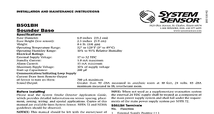
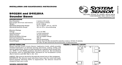
I Ohio Avenue St Charles Illinois 60174 FAX 630 377 6495 and mainTenanCe inSTrUCTiOnS Tone Sounder Base Diameter Height less sensor Temperature Range Humidity Range Ratings Supply Voltage Current Current Ripple Voltage Capacitance Loop Supply Draw from Remote Output Sensor to turn on Horn Output inches 15.2 cm inches 5.9 cm lb 181 gm to 120 0 to 49 to 93 Relative Humidity to 32 VDC mA maximum mA maximum of supply voltage maximum Greater than 90 dBA measured in anechoic room at 10 feet 24 volts 85 dBA minimum in UL reverberant room installing read the System Smoke Detector Application Guide provides detailed information on sensor spacing place zoning wiring and special applications Copies of this are available from System Sensor NFPA 72 and NEMA should be observed This manual should be left with the owner user of equipment The detector used with this base must be tested maintained regularly following NFPA 72 requirements detector should be cleaned at least once a year description B501BHT sounder base is used with System Sensor 200 500 Series sensor heads Refer to the appropriate manual more information on sensors B501BHT incorporates the distinctive three pulse tempo pattern fire alarm evacuation signal now required by NFPA for commercial and residential applications sounder base is intended for use with intelligent systems to the panel manual for the maximum allowable num of units per loop The sounder base requires an external supply with reverse polarity capability or a relay mod configured to reverse the power as in Figure 5 The con for the external supply terminals 1 and 2 and the loop terminals 3 and 4 are isolated to pre electrical interaction between them the sensor visible LEDs are latched on for approxi 10 seconds the associated horn sounds A loop of can be made to sound by reversing the polarity of the supply when configured as in Figure 4 and 5 When as in Figure 5 a loop of horns can also be made to by turning on the Intelligent Relay Module Supply Positive Supply Negative Comm Line In and Out Comm Line In and Out Base Interconnect When not used as a supplementary evacuation system external 24 VDC supply shall be treated as a component of main power supply system and shall fall under the require of the main power supply system per NFPA 72 Terminals Function 3 and 4 are used for the communication circuit the B501BHT directly to an electrical box using the kit supplied see Figure 2 sounder base is 1.1 inches deep Electrical boxes must 4 inches square by at least 11 inches deep 21 inches is A maximum space of 1 inch from the outside edge of electrical box to the inside edge of the drywall or ceiling is allowable Guidelines wiring must be installed in compliance with the National Code and the local codes having jurisdiction and not be of such length or wire size which would cause base to operate outside of its published specifications The used to connect smoke sensors to control panels accessory devices should be color coded to reduce the of wiring errors Improper connections can prevent system from responding properly in the event of a fire signal wiring the wiring between interconnected sensors modules it is recommended that the wire be no smaller 18 gauge 1.0 square mm Wire sizes up to 12 gauge 2.5 mm may be used with the base For best system per the power and wires and the communication wires should be twisted pair or shielded cable installed separate grounded conduit to protect the communication from electrical interference wire connections by stripping about 3 of insulation the end of the wire Then slide the bare end of the under the clamping plate and tighten the clamping screw Do NOT loop the wire under the clamping plate Figure 3 zone wiring of the sensor base should be checked before sensor heads are installed Check the wiring for continuity polarity in the base the individual sensor manual for the maximum sensor in temperature instructions External supply shown in normal standby configura in Figure 4 and 5 wiring diagram for a typical 2 wire intelligent system is in Figure 4 and 5 the monitor module is supervising external supply and bases must be tested after installation and as an inte part of periodic maintenance Test the B501BHT as follows Before testing notify the proper authorities that the sensor system is undergoing maintenance and there will be temporarily out of service Disable the system un maintenance to prevent unwanted alarms If configured as in Figure 4 or 5 reverse the polarity of the 24VDC supply If configured as in Figure 5 turn the Intelligent Relay Module All B501BHT bases on the should sound in approximately 10 seconds Latch the sensor LED on from the control panel That unit should sound in approximately 10 seconds There is approximately a 10 second delay built into the before sounding This delay is present whether control signal comes from the sensor or from the exter power supply polarity being reversed During automatic testing cycles the horn may sound if associated sensor is left in the test mode with LEDs on for more than 4 seconds Therefore it is neces to complete testing of each sensor within this 4 sec limit to prevent the horn from sounding 1 Terminal layout 2 mounting B501BHT ELECTRICAL BOX INCH SQUARE BOX 3 4 Wiring diagram Activates Sounder Base s Complies with UL268 has approved grouping for up to six B501BHT base with units When wired as a group any detector in the group has its LED latched on by the panel will cause other units in the group to sound This type of is accomplished by wiring the grouped devices to using terminal 5 Sounder Base Interconnect as shown the diagram Since a local grouping of horns is not supervised the can only be used as a supplementary evacuation system is not acceptable to group horns for primary alarm signaling A OPTIONAL WIRING SOUNDER INTERCONNECT MODULE SLC SLC A OPTIONAL WIRING OF UP TO 6 MODEL B501BHT TEMPORAL TONE SOUNDER BASES 5 Wiring diagram Activates Sounder Base s Intelligent Relay Module Ac All Sounder Bases Complies with UL 268 and UL 464 has approved grouping of up to six B501BHT bases with units When wired as a group any detector in the group has its LED latched on by the panel will cause other units in the group to sound This type of is accomplished by wiring the grouped devices to using terminal 5 Sounder Base Interconnect as shown the diagram Since a local grouping of horns is not supervised the can only be used as a supplementary evacuation sys It is not acceptable to group horns for primary alarm SOUNDER INTERCONNECT 2 SLC 2 2 1 1 SLC 1 MODULE SLC SLC LISTED IS A STANDARD RELAY CONFIGURED TO THE POWER OF UP TO 6 MODEL B501BHT TEMPORAL TONE SOUNDER BASES