System Sensor D2 Manual
File Preview
Click below to download for free
Click below to download for free
File Data
| Name | system-sensor-d2-manual-7512968340.pdf |
|---|---|
| Type | |
| Size | 1.88 MB |
| Downloads |
Text Preview
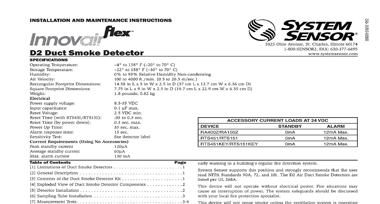
I 3825 Ohio Avenue St Charles Illinois 60174 FAX 630 377 6495 to 158 F to 70 C to 158 F to 70 C to 93 Relative Humidity Non condensing to 4000 ft min 0.5 to 20.3 m sec in L x 5 in W x 2.5 in D 37 cm L x 12.7 cm W x 6.36 cm D in L x 9 in W x 2.5 in D 19.7 cm L x 22.9 cm W x 6.35 cm D pounds 0.82 kg AND MAINTENANCE INSTRUCTIONS VDC max VDC min to 0.3 sec sec max sec max sec detector label Duct Smoke Detector Temperature Temperature Velocity Footprint Dimensions Footprint Dimensions supply voltage capacitance Voltage Time with RTS451 RTS151 Time by power down Up Time response time Test Requirements Using No Accessories standby current standby current alarm current mA of Contents Limitations of Duct Smoke Detectors 1 General Description 1 Contents of the Duct Smoke Detector Kit 1 Exploded View of Duct Smoke Detector Components 2 Detector Installation 2 Sampling Tube Installation 3 Measurement Tests 3 4 Field Wiring 4 Detector Status Indicator 4 Verification of Operator 5 Dectector Cleaning Procedures 5 Sensor Replacement 6 Optional Accessories 6 Diagrams 4,6 D2 model is a photoelectric detector approved for an extended air speed of 100 to 4000 feet per minute 0.5 m s to 20.3 m s and an operational range of to 158 to 70 INSTALLING System Sensor Applications Guide for Duct Smoke Detectors HVAG53 provides detailed information on detector spacing placement zoning and special applications This manual is available online at www sys NFPA Standards 72 and 90A should also be referenced for information This manual shall be left with the owner user of this equipment This detector must be tested and maintained regularly following 72 requirements The detector must be tested an maintained regularly NFPA 72 requirements According to NFPA the detector should be inspected semiannually and functionally tested at least once a year may need to be more frequent depending on the air quality of the duct air LIMITATIONS OF DUCT SMOKE DETECTORS 6 National Fire Protection Association has established that DUCT DETEC MUST NOT BE USED AS A SUBSTITUTE FOR OPEN AREA DETECTOR as a means of providing life safety Nor are they a substitute for CURRENT LOADS AT 24 VDC Max Max Max warning in a building regular fire detection system Sensor supports this position and strongly recommends that the user NFPA Standards 90A 72 and 101 The D2 Air Duct Smoke Detectors are per UL 268A device will not operate without electrical power Fire situations may an interruption of power The system safeguards should be discussed your local fire protection specialist device will not sense smoke unless the ventilation system is operating the cover is installed this detector to function properly it MUST be installed according to the in in this manual Furthermore the detector MUST be operated within electrical and environmental specifications listed in this manual Failure comply with these requirements may prevent the detector from activating smoke is present in the air duct GENERAL DESCRIPTION introduced into the air duct system will be distributed throughout the building Smoke detectors designed for use in air duct systems are used sense the presence of smoke in the duct D2 Duct Smoke Detector utilizes photoelectric technology for the de of smoke This detection method when combined with an efficient design samples air passing through the duct allowing detection of a hazardous condition When sufficient smoke is sensed an alarm is initiated and appropriate action can be taken to shut off fans change over air handling systems etc These actions can facilitate management of toxic smoke and fire gases throughout the areas served the duct system DETECTOR FEATURE SET Utilizes 2151 plug in head Sampling tubes installed from front or rear Compatible with existing accessories CONTENTS OF THE DUCT SMOKE DETECTOR KIT Three 10 sheet metal screws for mounting Drilling template One sampling tube end cap One plastic exhaust tube board assembly and covers FIGURE 1 EXPLODED VIEW OF DUCT SMOKE DETECTOR COMPONENTS TUBE seperately TUBE TERMINALS HEAD MODULE COVER TEST LOCATION A sampling tube must be ordered to complete the installation It must the correct length for the width of the duct where it will be installed See Ta 1 on page 3 to determine the inlet tube required for different duct widths DETECTOR INSTALLATION VERIFY DUCT AIR FLOW DIRECTION AND VELOCITY D2 detectors are designed to be used in air handling systems having air of 100 to 4000 feet per minute Duct widths from 6 inches to 12 feet be accommodated Be sure to check engineering specifications to ensure the air velocity in the duct falls within these parameters If necessary use velocity meter anemometer to check the air velocity in the duct DETERMINE MOUNTING LOCATION CONFIGURATION ducts wider than 18 inches it is recommended that the detector be downstream of a bend obstruction in the duct or the supply or air inlet Installation of duct detectors can be on or within a commercial rooftop heating and air conditioning system fire smoke dampers economizers They may be mounted in either the supply and or return air as determined by local code a suitable location is selected determine if the detector is to be mounted a side by side configuration or a top over bottom as shown in Figure 2 If mounting in the square configuration the rear attachment screw rotate the unit at hinge and replace the into the new attachment hole as shown in Figure 2 Do NOT remove hinge screw during this process Final installation approval shall be based passing section 10.4.2 and 10.4.4 tests HOUSING COVER 2 SCREW AND PIVOT AS SHOWN BELOW SCREW SECURE DETECTOR PLACE DRILL THE MOUNTING HOLES the paper backing from the mounting template supplied Affix the tem to the duct at the desired mounting location Make sure the template lies and smooth on the duct FOR RECTANGULAR SIDE BY SIDE MOUNTING CONFIGURATION punch at 4 target centers 2 for sampling tubes and 2 for rectangular configuration mounting tabs as shown on mounting template pilot holes at target centers and cut two 1.375 inch diameter holes us a 13 8 inch hole saw or punch Drill 156 inch diameter holes using a 5 32 drill at target centers FOR SQUARE TOP OVER BOTTOM MOUNTING CONFIGURATION punch at 4 target centers 2 for sampling tubes and 2 for square configuration mounting tabs as shown on mounting template Drill holes at target centers and cut two 1.375 inch diameter holes using a inch hole saw or punch Drill 156 inch diameter holes using a 5 32 inch at target centers If desired drill an additional 156 inch h