System Sensor DNRHS Manual
File Preview
Click below to download for free
Click below to download for free
File Data
| Name | system-sensor-dnrhs-manual-6587312490.pdf |
|---|---|
| Type | |
| Size | 1.95 MB |
| Downloads |
Text Preview
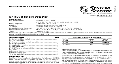
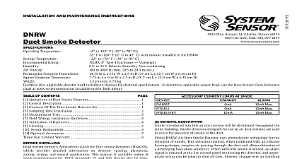
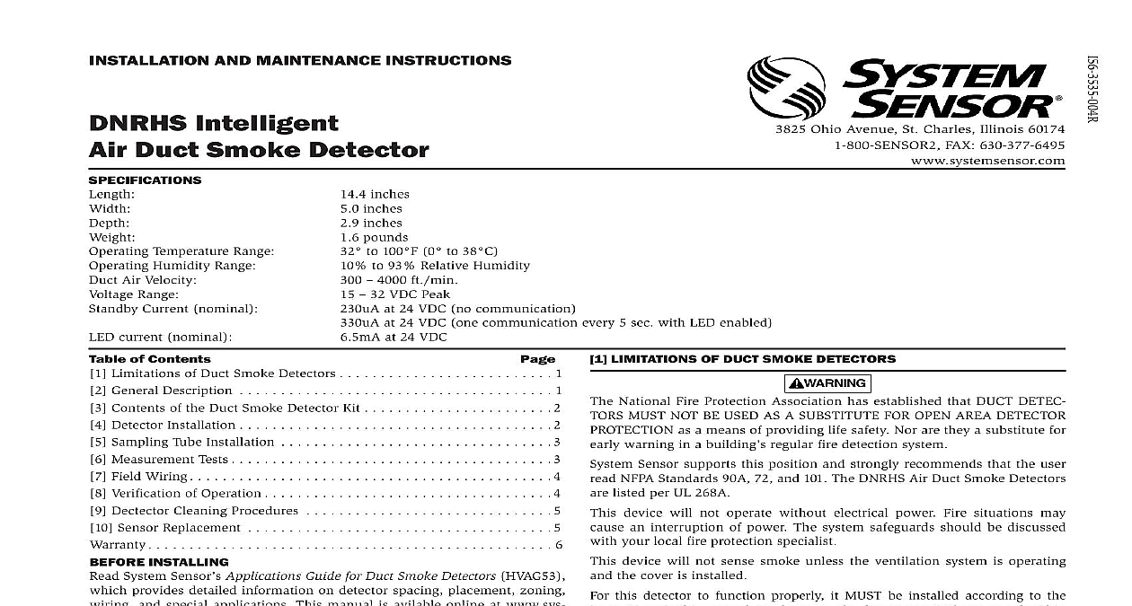
INSTALLATION AND MAINTENANCE INSTRUCTIONS Intelligent Duct Smoke Detector Temperature Range Humidity Range Air Velocity Range Current nominal current nominal 4 inches 0 inches 9 inches 6 pounds to 100 0 to 38 to 93 Relative Humidity 4000 ft min 32 VDC Peak at 24 VDC no communication at 24 VDC one communication every 5 sec with LED enabled 5mA at 24 VDC Ohio Avenue St Charles Illinois 60174 FAX 630 377 6495 systemsensor com of Contents Limitations of Duct Smoke Detectors 1 General Description 1 Contents of the Duct Smoke Detector Kit 2 Detector Installation 2 Sampling Tube Installation 3 Measurement Tests 3 Field Wiring 4 Verification of Operation 4 Dectector Cleaning Procedures 5 Sensor Replacement 5 6 INSTALLING System Sensor Applications Guide for Duct Smoke Detectors HVAG53 provides detailed information on detector spacing placement zoning and special applications This manual is avilable online at www sys com NFPA Standards 72 76 and 90A should also be referenced for information This manual should be left with the owner user of this equipment sensors must be tested after installation and periodically thereafter Test methods must satisfy the Authority Having Jurisdiction AHJ Sensors maximum performance when tested and maintained in compliance with 72 1 TUBE LIMITATIONS OF DUCT SMOKE DETECTORS National Fire Protection Association has established that DUCT DETEC MUST NOT BE USED AS A SUBSTITUTE FOR OPEN AREA DETECTOR as a means of providing life safety Nor are they a substitute for warning in a building regular fire detection system Sensor supports this position and strongly recommends that the user NFPA Standards 90A 72 and 101 The DNRHS Air Duct Smoke Detectors listed per UL 268A device will not operate without electrical power Fire situations may an interruption of power The system safeguards should be discussed your local fire protection specialist device will not sense smoke unless the ventilation system is operating the cover is installed this detector to function properly it MUST be installed according to the in this manual Furthermore the detector MUST be operated within electrical and environmental specifications listed in this manual and the head installation manual Failure to comply with these requirements prevent the detector from activating when smoke is present in the air duct GENERAL DESCRIPTION HVAC system supplies conditioned air to virtually every area of a building introduced into this air duct system will be distributed to the entire Smoke detectors designed for use in air duct systems are used to the presence of smoke in the duct In facilities with large air changes per airflow can carry smoke particles directly to the HVAC system Per NFPA Very Early Warning Fire Detection VEWFD sensors shall be installed to return air from the space The DNRHS can be installed to monitor the air from the space in order to meet NFPA 76 requirements COMPARTMENT COMPARTMENT COVER MODULE HEAD SENSOR HEAD IS ONLY ON SPECIFIED MODELS MODULE COVER DNRHS Air Duct Smoke Detector uses a 7251 laser smoke sensor This detection method combined with an efficient housing design that air passing through a duct provides early detection of a developing condition When sufficient smoke is sensed an alarm signal is ini at the fire control panel monitoring the detector and appropriate action be taken to shut off fans and blowers change over air handling systems This can prevent the distribution or isolation of toxic smoke and fire gases the areas served by the duct system as well as provide an alert of developing hazardous condition in a facility LEDs on each detector latch ON to provide a local alarm indication There also a remote alarm output for use with auxiliary devices The DNRHS remote test capability with the RTS451 RTS151 RTS451KEY RTS151KEY Test Station DETECTOR FEATURE SET Utilizes plug in head Sampling tubes install from front and rear Compatible with existing accessories Able to address detector per code switches on sensor head CONTENTS OF THE DUCT SMOKE DETECTOR KIT Sensor power side and covers use appropriate sensor per the system panel Three 10 sheet metal screws for mounting Drilling template One sampling tube end cap One plastic exhaust tube DCOIL Test Coil DETECTOR INSTALLATION 2 APPLICATION EXAMPLES VIEWED FROM ABOVE Smoke Sensor A DST sampling tube must be ordered to complete the installation It be the correct length for the width of the duct where it will be installed See 1 on page 3 to determine the inlet tube required for different duct widths VERIFY DUCT AIR FLOW DIRECTION AND VELOCITY DNRHS detectors are designed to be used in air handling systems hav air velocities of 300 to 4000 feet per minute Duct widths from 6 inches to feet can be accommodated Be sure to check engineering specifications to that the air velocity in the duct falls within these parameters If neces use a velocity meter anemometer to check the air velocity in the duct DNRHS duct smoke detector should be mounted as follows 3 PLENUM DIMENSION AND DETECTOR POSITION FROM SIDE Location Mount detector on the room side up stream of any air filter Mounting detector after filter may filter out smoke particles and not recommended Coverage Each detector pipe length should be mounted along the longer of the return air opening length direction One detector and standard pre drilled pipe length should be installed for every 2ft return air opening width When more than one detector is required greater than 2ft detector housings should be staggered on op ends of the opening length refer to Figure 2 Install detectors at the proper height within the duct plenum per the shown in Figure 3 Hole Direction holes facing directly into flow for positive pressure effect Ensure adequate pressure differential across the detector housing accord to section 8 1 of this document 4 SCREW AND PIVOT AS SHOWN BELOW SCREW SECURE DETECTOR PLACE DETERMINE MOUNTING LOCATION AND CONFIGURATION ducts wider than 18 inches it is recommended that the detector be downstream of a bend obstruction in the duct or the supply or air inlet Installation of duct detectors can be on or within a commercial rooftop heating and air conditioning system fire smoke dampers economizers They may be mounted in either the supply and or return air as determined by local code a suitable location is selected determine if the detector is to be mounted a side by side configuration or a top over bottom as shown in Figure 4 If mounting in the square configuration the rear attachment screw rotate the unit at hinge and replace the into the new attachment hole as shown in Figure 4 Do NOT remove hinge screw durin