System Sensor DUCTSD240

File Preview
Click below to download for free
Click below to download for free
File Data
| Name | system-sensor-ductsd240-9827436015.pdf |
|---|---|
| Type | |
| Size | 888.34 KB |
| Downloads |
Text Preview
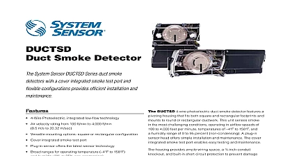
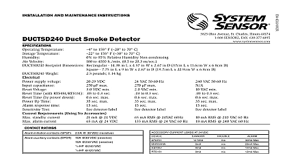
DUCTSD240 Photoelectric Smoke Detector System Sensor DUCTSD Series duct smoke detectors a cover integrated smoke test port and exible gurations simpli es installation and maintenance 4 Wire Photoelectric integrated low flow technology Air velocity rating from 100 ft min to 4,000 ft min m s to 20.32 m sec Versatile mounting options square or rectangular configuration Cover integrated smoke test port Plug in sensor offers the latest sensor technology Broad ranges for operating temperature to 158 and 0 to 95 non condensing Patented sampling tube installs from the front or back of the with no tools required Increased wiring space with an added conduit knockout One easy access Test Reset button Patented interconnect feature for multi fan shutdown High contrast terminal designations and wiring diagram label on of power side cover make wiring easy Built in short circuit protection from operator wiring errors Two DPDT Form C relay contacts 24 VAC DC or 240 VAC Backward compatibility with existing products remote accessories Listings DUCTSD240 4 wire photoelectric duct smoke detector a pivoting housing that ts both square and rectangular and mounts to round or rectangular ductwork This unit smoke in the most challenging conditions operating in ow speeds of 100 to 4,000 feet per minute temperatures of 158 and a humidity range of 0 to 95 percent non condensing plug in sensor head offers simple installation and maintenance cover integrated smoke test port enables easy testing and housing provides ample wiring space a conduit and built in short circuit protection to prevent damage sensitive components during installation High contrast terminal make wiring easy As many as 30 DUCTSD240 can be interconnected When one unit senses smoke all detectors will switch their relays only the detector smoke will go into alarm thus pinpointing the alarm location easy access Test Reset button and smoke test port makes it to test the unit with the cover on The power board has an that can be used to indicate the status of the sensor Standby Trouble and Alarm The DUCTSD240 product line is with previous System Sensor models including remote accessories Duct smoke detectors are NOT a substitute for open smoke detectors NOT a substitute for early warning detection a replacement for a building regular re detection system to NFPA 72 and 90A for additional information Duct Smoke Detector Specifications Specifi cations air duct smoke detector shall be a System Sensor DUCTSD240 Photoelectric Duct Smoke Detector The detector housing shall be UL per UL 268A speci cally for use in air handling systems The exible housing of the duct smoke detector shall t square and rectangular The detector shall operate at air velocities of 100 feet per minute to 4,000 feet per minute 0.5 to 20.32 meters per second The shall be capable of controlling up to 30 air handling systems when interconnected with other detectors The detector shall be capable of a trouble signal in the event that the front cover is removed It shall be capable of local testing via magnetic switch test button on cover cover integrated smoke test port or remote testing using the RTS151 or the RTS151KEY Remote Test Station Terminal connections be of the strip and clamp method suitable for 12 AWG wiring Specifi cations Rectangular Dimensions Square Dimensions Temperature Range Temperature Range Humidity Range Duct Velocity Ratings supply voltage capacitance voltage time by power down up time response time test requirements using no accessories standby current alarm current in 37 cm Length 5 in 12.74 cm Width 2.5 in 6.36 cm Depth in 19.7 cm Length 9 in 22.9 cm Width 2.5 in 6.35 cm Depth lbs 1.14 kg to 158 to 70 to 158 to 70 to 95 relative humidity non condensing to 4,000 ft min 0.5 to 20.32 m sec VAC 50 Hz VAC min sec max sec max sec detector label VDC max VDC min sec max sec max sec detector label VAC 50 Hz max VAC min sec max sec max sec detector label mA RMS 240 VAC 60 Hz mA RMS 240 VAC 60 Hz mA RMS 24 VAC 60 Hz mA RMS 24 VAC 60 Hz mA 24 VDC mA 24 VDC A 30 VDC resistive A 30 VDC resistive 10 A 250 VAC resistive HP 240 VAC HP t VAC Ratings initiation contacts SPST auxiliary contacts DPDT Alarm auxiliary contacts shall not be connected to initiating circuits of control panels Use the alarm initiation contact for this purpose contacts SPDT Current Loads at 24 VDC Any combination of accessories may be used such that the given accessory loads are mA mA mA mA 12 mA mA max mA max mA max mA max A 30 VDC resistive 2.0 A 125 VAC resistive mA or less at the Aux output and 50 mA or less at the Alarm output the DUCTSD240 Sampling Tube DUCTSD240 sampling tube may be installed from the front or back of the detector The tube locks securely into place and can be by releasing the front or rear locking tab front locking tab shown below right for 4 Wire Duct Smoke Detector and Accessories INPUTS NOTE 1 INPUTS NOTE 1 CONTACTS FAN SHUTDOWN ETC NOTE 2 A B CONTACTS FAN SHUTDOWN ETC NOTE 2 A B CONTACTS 3 C N O CONTACTS 3 C N O RESISTOR BY LISTED PANEL 4 C N O 4 C N O DETECTOR IN THE LOOP DETECTOR IN THE LOOP 1 24V Power Inputs accept a non polarized 24VDC or 24VAC 240VAC Power Inputs accept only 240VAC Connect power source to appropriate terminals each detector See speci cations for additional power information Please note that a varistor is put across 240 VAC terminals to protect the product from transient 2 Auxiliary contacts shown in standby position Contacts during alarm as indicated by arrows Auxiliary are not to be used for connection to the control See speci cations for contact ratings refer to the corresponding installation manual for accessory diagrams 3 Supervisory contacts shown in standby position Open indicate a trouble condition to the panel See cations for contact ratings 4 Alarm Initiation contacts shown in standby position Closed indicate an alarm condition to the panel See cations for contact ratings Interconnect Notes When using the interconnect feature all interconnected units must be powered using the same independent supply Polarity must be maintained throughout the interconnect wiring Connect the INT terminal on unit 1 to the INT terminal on unit 2 and so Similarly connect the INT AUX terminal on unit 1 to the INT AUX terminal on unit 2 and so on Up to 30 DUCTSD240 units may be interconnected NOTE Alarm can be reset only at the initiating device and not at the interconnected devices Sensor provides system exibility with a variety of accessories including two remote test stations and several different means of and audible system annunciation As with our duct smoke detectors all duct smoke detector accessories are UL listed UL S4011 UL S2522 UL S4011 UL S2522 UL S4011 UL S4011 Information No