System Sensor EA-CT Manual
File Preview
Click below to download for free
Click below to download for free
File Data
| Name | system-sensor-ea-ct-manual-2754069183.pdf |
|---|---|
| Type | |
| Size | 1.08 MB |
| Downloads |
Text Preview
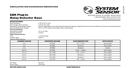
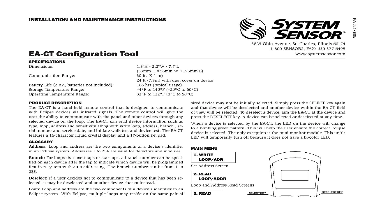
INSTALLATION AND MAINTENANCE INSTRUCTIONS Configuration Tool Range Life 2 AA batteries not included Temperature Range Temperature Range H W L ft 9.1 m ft 7.3m with dust cover on device hrs typical usage to 140 to 60 to 122 0 to 50 3825 Ohio Avenue St Charles Illinois 60174 FAX 630 377 6495 device may not be initially selected Simply press the SELECT key again that device will be deselected and another device within the EA CT field view will be selected To deselect a device aim the EA CT at the device and the DESELECT key A device can be selected or deselected at any time a device is selected by the EA CT the LED on the device will change a blinking green pattern This will help the user ensure the correct Eclipse is selected The only exception is the mini monitor module This unit will temporarily turn off because it does not have a bi color LED DESCRIPTION EA CT is a hand held remote control that is designed to communicate Eclipse devices via infrared signals The remote control will give the the ability to communicate with the panel and other devices through any device on the loop The EA CT can read device information such as loop address and sensitivity along with write loop address branch se number and service date and initiate walk test and device test The EA CT a 16 character liquid crystal display and a 17 button keypad Loop and address are the two components of a device identifier an Eclipse system Addresses 1 to 254 are valid for detectors and modules For loops that use t taps or star taps a branch number can be speci on each device after the tap to indicate which device will be programmed in a system with auto addressing The branch number can be from 1 to If a user decides not to communicate to a device that has been se it may be deselected and another device chosen instead Loop and address are the two components of a device identifier in an system With Eclipse multiple loops may reside on the same pair of Loops can be numbered 1 to 254 Key If a user misplaces their PIN number the EA CT can generate a or master key that will allow technical support to provide a temporary number for access COMM RETRY This message will appear on the configuration tool if the message was not transmitted properly to the receiving device the steps to complete the desired action number The EA CT is equipped with a personal identification number when enabled prevents unauthorized use of the device Since the EA CT can conceivably have more than one detector module within its field of view only one device can be chosen or from the group The select key is used to choose the device which the EA CT will communicate Pressing the SELECT key more than will alternately select each device within the EA CT range A selected is ready to receive communications from the EA CT The target is the address of the device that you would like to com with using the EA CT The target is not necessarily the device that is or a device in the line of sight INSTRUCTION the PWR button on the EA CT For first time users or devices without PIN number the main menu will be displayed To be able to set your PIN refer to the PIN enable disable 7.1 section of this manual The menu consists of seven choices for the user You can select each choice pressing the up or down keys to highlight your selection and pressing enter by pressing the number of the selected item EA CT automatically shuts down after 200 seconds of non use communication is enabled the device must be by the EA To select a device aim the EA CT at the device and press the SELECT key situations where there is more than one device in close proximity the de KEY UP KEY KEY KEY DOWN KEY and Address Read Screens MENU WRITE Address Screen READ READ Screen WRITE TEST CHOOSE Service Date Screen Target Loop Address TOOL Options Menu Mode Options BUTTON There must be a clear line of sight between the EA CT and the device is communicating with WRITE LOOP ADDRESS option is for assigning an Eclipse device to a certain loop and address this option is chosen by pressing ENTER the following screen is dis user may then enter the specific address and loop designation desired for device The maximum address and loop numbers that can be used are After an address is entered point the EA CT to the device whose address wish to set Press the SELECT key to select that device When the ENTER is pressed the device will start a communication If there is a problem the communication a trouble screen will be displayed COMM retry press the ENTER key again and the EA CT will attempt to re connect the device If the address is accepted the following screen will be displayed NEW SET this point if the user wishes to increase the address number the up arrow should pressed and the following screen will appear with the address incremented at this point the user selects another unit using the SELECT button by ENTER the incremented address and the same loop will be recorded the new unit same functionality is available by using the down arrow READ LOOP ADDR ENTER at this menu option will give the user the ability to read a Eclipse device to see what its current address and loop designation When this choice is made the screen will prompt the user to point to the that is to be read Point to the device that you want to read and press ENTER key If the communication is successful the screen will display similar to the following example 147 123 there is a problem with the communication trouble screen is received COMM retry press the enter key again and the EA CT will attempt to communicate to the device READ DEVICE menu option will indicate for a selected device its type address loop branch marker When ENTER is pressed on this option the first screen comes up is similar to 147 123 that is not the correct loop or address the user can press ESC to go back to Address Set Screen to make the change If that is the correct setting and selected device is a device with isolators the down arrow key is pressed to the branch setting similar to the example that is not the correct branch number the user can go to the Branch Setting by pressing enter again to make the appropriate changes BRANCH set a branch marker on a selected device press the enter key on this op and after the set new branch screen is displayed the following screen come up the branch number that is desired Point the EA CT at the device that to receive the branch marker Press enter and after a moment the EA CT display set display the new branch number press ESC twice XXX If the selected device does not contain isolators the following serial screen will appear immediately following the loop and address view 0XXX next screen that comes up will depend on the device type the device is a heat detector the following display will appear the device is a heat detector the user can press the down key again to find whether the device is set at a rate of rise or a fixed temperature setting the detector is configured to be a rate of rise detector the following screen appear the detector is configured at a fixed heat temperature setting and is on the menu setting the following screen will appear the detector is configured at a fixed heat temperature setting and is on the menu setting the following screen will appear the device is a photo heat detector the following screen will appear the down arrow is pressed again a screen similar to this one will show whether device is configured to Acclimate 0.5 4.0 screen shows the sensitivity level of the photo heat detector The AHIS the upper limit of the Acclimate sensitivity range in percent per foot The indicates the lower limit of the Acclimate sensitivity range in perce