System Sensor EBS Manual

File Preview
Click below to download for free
Click below to download for free
File Data
| Name | system-sensor-ebs-manual-7091456382.pdf |
|---|---|
| Type | |
| Size | 1.79 MB |
| Downloads |
Text Preview
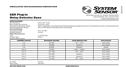
I Ohio Avenue St Charles Illinois 60174 FAX 630 377 6495 in 17.4 cm in 4.1 cm to applicable sensor Operating Temperature Range using the Base Sensor Cross Reference Chart at systemsensor com to 93 relative humidity Non condensing to 32 VDC maximum than 85 dBA minimum measured in a UL reverberant room at 10 feet 24 Volts in continuous tone 1 TERMINAL LAYOUT AND MAINTENANCE INSTRUCTIONS to 33 VDC VFWR maximum mA maximum Sounder Base Diameter Height less sensor Temperature Range Humidity Range Supply Electrical Ratings Supply Voltage Current Current Electrical Ratings Operating Voltage Standby Current Output INSTALLING System Sensor Applications Guide for System Smoke Detectors which provides detailed information on detector spacing place zoning wiring and special applications This document is available from System Sensor NFPA 72 guidelines should be observed This manual should be left with the owner user of this equipment The detector used with this base must be tested and maintained following NFPA 72 requirements The detector should be cleaned at once a year DESCRIPTION sounder base was designed specifically to meet the needs of dwelling unit It offers maximum flexibility in configuration and operation to or exceed the requirements of UL268 and UL464 sounder base is capable of producing either the distinctive three pulse pattern ANSI Temporal 3 fire alarm signal now required by NFPA for commercial and residential applications or a continuous tone by simply the included jumper from the device sounder base is intended for use with intelligent systems The sounder requires an external 24 VDC power supply The connections for the power supply and the communication loop are isolated to prevent interaction between them Refer to the panel manual for maximum number of units per loop For NFPA72 Installations the Temporal 3 tone should be used for public evacuation When not used as a supplementary evacuation system the external 24 supply shall be treated as a component of the main power supply system shall fall under the requirements of the main power supply system per 72 TERMINALS Function Comm Positive Comm Line In and Out Positive Comm Line Out and In External Supply Positive External Supply Negative the mounting plate directly to an electrical box The plate will mount to 4 inch square 4 inch octagon 3 1 2 inch octagon single gang and gang junction boxes Connect field wiring to terminals as shown in Figure 1 and 3 Attach the mounting plate to the junction box as shown in Figure 2 To mount the sounder base hook the tab on the sounder base to the groove the mounting plate Then swing the sounder base into position to engage the pins on the with the terminals on the mounting plate Secure the sounder base by tightening the mounting screws Install a compatible smoke detector as described in the installation manual the detector AND WIRING GUIDELINES wiring must be installed in compliance with all applicable local codes any special requirements of the authority having jurisdiction Proper wire should be used The conductors used to connect smoke detectors to panels and accessory devices should be color coded to reduce the like of wiring errors Improper connections can prevent a system from re properly in the event of a fire signal wiring the wiring between interconnected sensors or modules is recommended that the wire be no smaller than 18 AWG 0.823 square Wire sizes up to 12 AWG 3.31 square mm may be used with the base base will be shipped with the screw terminals set for 14 AWG wiring If AWG wire is used back out the screws to allow the wire to fit beneath the plates Grouping extra connections are required for grouping However the panel must be to set up a group to sound their horns together The panel can be up for a device to activate only the remote annunciator of the device that the alarm or to activate the remote annunciators of all the devices on loop The latter will provide horn grouping for a loop and bases must be tested after installation and as an integral part of maintenance Test the EBS as follows Single Horn Test Configure the panel to only activate the remote annun of the alarm test detector Activate the detector base will sound less than 1 second Multiple Horn Test Configure the panel to activate all remote annuncia on the loop when the panel detects an alarm or test Initiate a test all horns on the loop will sound simultaneously Grouping horns together can only be used as a supplementary evacu system It is not acceptable to group horns for primary alarm signaling electrical connections by stripping about 3 8 inch 10 mm of insulation the end of the wire use strip gauge molded in base Then slide the wire the clamping plate and tighten the clamping plate screw Do not loop wire under the clamping plate See Figure 4 the zone wiring of all bases in the system before installing the detec This includes checking the wiring for continuity correct polarity ground testing and performing a dielectric test base includes an area for recording the zone address and type of detec being installed This information is useful for setting the detector head and for verification of the detector type required for that location all detector bases have been wired and mounted and the loop wiring been checked the detector heads may be installed in the bases AND MAINTENANCE and bases must be tested after installation and as an integral part of periodic maintenance program Test as follows Before testing notify the proper authorities that the smoke sensor is undergoing maintenance and therefore will be temporarily out of Disable the system undergoing maintenance to prevent unwanted If configured as in Figure 3 reverse the polarity of the external 24VDC sup All EBS bases on the loop should sound Latch the detector LED on from the control panel That individual detector should sound performing maintenance on connected smoke detectors carefully note location and address of each removed detector 2 MOUNTING 3 WIRING DIAGRAM ACTIVATES SOUNDER BASE S COMPLIES WITH UL268 AND UL464 A OPTIONAL WIRING SOUNDER INTERCONNECT MODULE SLC SLC LISTED SLC SLC POWER POWER A OPTIONAL WIRING GROUPING OF UP TO 6 MODEL EBS SOUNDER BASES OF LINE RELAY OR EQUIVALENT 4 5A ACTIVATING THE TAMPER RESIST FEATURE LEVER FEATURE Do not use the tamper resist feature if the removal tool will be used detector base includes a tamper resist feature that prevents removal of detector from the base without using a small screwdriver or similar tool activate this feature use needle nose pliers to break the tab on the detector as shown in Figure 5A Then install the detector remove the detector from the base once the tamper resist feature has been insert a small bladed screwdriver into the slot from the top and down on the lever see Figure 5B This allows the detector to be rotated for removal tamper resist feature can be defeated by breaking and removing the plastic from the base However this prevents the feature from