System Sensor EPS40, EPS40-2, EPS120-1, and EPS120-2 Manual

File Preview
Click below to download for free
Click below to download for free
File Data
| Name | system-sensor-eps40-eps40-2-eps120-1-and-eps120-2-manual-3674829051.pdf |
|---|---|
| Type | |
| Size | 766.68 KB |
| Downloads |
Text Preview
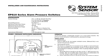
EPS40 Series and EPS120 Series Pressure Switches 3825 Ohio Avenue St Charles Illinois 60174 FAX 630 377 6495 AND MAINTENANCE INSTRUCTIONS Ratings Dimensions Temperature Range Service Pressure Range Rating Differential Read Carefully and Save A 1 2 HP 125 250 VAC 125 250 VAC LPCB ONLY 6 12 24 VDC Figure 1 to 160 EPS40 2 PSI EPS120 2 300 PSI EPS40 2 PSI EPS120 2 10 200 PSI 4x Indoor or Outdoor Use 4 Indoor or Outdoor Use EPS40 2 EPS120 2 PSI at 10 PSI PSI at 100 PSI PSI at 10 PSI PSI at 200 PSI instruction manual contains important information about the installa and operation of supervisory pressure switches Purchasers who install for use by others must leave this manual or a copy of it with the user all instructions carefully before installation following only those instruc that apply to the model you are installing installing any alarm device be thoroughly familiar with 72 National Fire Alarm Code 13 25 of Sprinkler Systems Inspection Testing and Maintenance of Water based Fire Protec Systems 13D Standard for 1 and 2 Family Dwellings and Manufactured Homes 13R Standard for Multi family Dwellings applicable NFPA standards local codes and the requirements of the having jurisdiction to follow these directions may result in failure of the device to report alarm condition System Sensor is not responsible for devices that have improperly installed tested or maintained not use in potentially explosive atmospheres Do not leave unused wires exposed is held on by two screws pressure changes a diaphragm actuates 1 or 2 snap action switches The switch actuation is determined by adjustment settings Remove Cover Mounting the Switch The device is designed to be mounted in the upright position side mounting also acceptable Locate it where vibration shock and mechanical loading minimal Refer to piping diagram above Fig 2 and 3 Mount the device directly to the line via the 1 NPT pressure con The use of teflon pipe sealant tape is recommended Be sure fitting is tight enough to prevent leaks Apply tightening torque to the black plastic hex portion of the device voltage Electrocution hazard Do not handle live AC wiring or work on device to which AC power is applied Doing so may result in severe injury death When utilizing switches at voltages greater than 74 VDC or VAC means to provide all pole disconnection must be incorporated in field wiring such as a circuit breaker Wire the device in accordance with the National Electrical Code Two 7 8 conduit connection holes have been provided in the mounting to accept standard 1 conduit fittings one is removable knock out If a NEMA 4 UL 4x waterproof unit is required waterproof flex metallic conduit and appropriate conduit fittings must be used Rec connectors are Thomas and Betts PN 5332 180 coupling 5352 90 coupling and PN 5262 seal ring Connect wiring to terminals see Figure 4 and Table 1 to Factory Settings 1 PRESSURE SWITCH BASIC DIMENSIONS 2 SCREW ADJUSTMENT NPT 2 TYPICAL PIPING DIAGRAM FOR EPS40 1 EPS40 2 3 TYPICAL PIPING DIAGRAM FOR EPS120 1 EPS120 2 TO SUPERVISORY OF FIRE ALARM PANEL TO ALARM CIRCUIT FIRE ALARM PANEL FOR ALARM OFF Y SYSTEM Y Y ALARM OFF LINE 2 SETTINGS PSI SW2 Switch 1.5 1.5 112.5 112.5 SW1 Switch 2.5 128.5 MODEL EPS40 1 AND EPS120 1 Install pressure switch as stated in portion of instruc manual Attach pressure test source to system Back off locking screw see Fig 4 to allow main adjustment wheel to freely Test the switch for the set point by introducing 40 PSI pressure from the test source for the EPS40 1 115 PSI for the EPS120 1 Decrease slowly until the switch trips Rotate main adjustment wheel 5 counterclockwise to increase pressure and retest by first intro a higher pressure than desired and slowly reducing pressure until switch trips Repeat process until switch trip point is at desired pres setting Each number represents an approximate trip point change 1.8 PSI for the EPS40 1 and 6.6 PSI for the EPS120 1 For each 1 2 of the adjustment wheel the trip point setting changes by ap 11 PSI for the EPS40 1 and 40 PSI for the EPS120 1 Retest the set point several times to ensure accuracy of setting Re seat locking screw 4 SWITCH LOCATION 1 2 I T WIRE AS SHOWN FOR OF CONNECTION NOT ALLOW STRIPPED WIRE TO EXTEND BEYOND HOUSING DO NOT WIRES MODEL EPS40 2 AND EPS120 2 Install pressure switch as stated in portion of instruc manual Attach pressure test source to system Back out the locking screw see Fig 4 to allow main adjustment wheel turn freely Option 1 Adjust nominal pressure setting without affecting PSI window Adjust main adjustment wheel see Fig 5 to desired setting using source i e valve or air maintenance device Turn main adjustment wheel counterclockwise to increase see arrow mounting base or clockwise to decrease pressure Each number main adjust wheel represents an approximate window shift of 1.8 for EPS40 2 and 6.6 psi for EPS120 2 For each 1 2 rotation of the wheel the window changes by approximately 11 psi for and 40 psi for EPS120 2 Retest the set point several times to ensure the accuracy of the setting 2 Adjust pressure window size and nominal setting of pres window Adjust main adjustment wheel see Fig 5 until high switch SW1 at desired pressure using pressure test source valve or air main device Refer to step B from Option 1 Decrease pressure until the low switch trips SW2 Adjust 1 4 low pressure hex head nut see Fig 5 to either increase or decrease clockwise the window size the low will be affected The approximate sensitivity of the hex screw adjustment 1 2 turn 5 A maximum of 30 psi is attainable Retest the set points several times to ensure the accuracy of the settings adjust as necessary Re seat locking screw EPS40 models are able to be set to a range within 8 100psi only when with Victaulic series 768 and 769 FireLock NXT valves pre set for use low pressure actuators When used on Victaulic series 768 and 769 NXT all units must be 100 tested to verify pressure setting Both main adjustment wheel and low pressure adjusting screw See Figure 5 to be customer set and tested to insure proper functionality For pres setting instructions refer to Installation section for dual switch models in manual 1 ELECTRICAL CONNECTIONS REFERENCED AT FACTORY EPS40 1 EPS120 1 EPS40 2 EPS120 2 AT NORMAL SYSTEM PRESSURE AT TRIP POINT AT NORMAL SYSTEM PRESSURE 1 AT HIGH TRIP POINT AT LOW TRIP POINT 5 ADJUSTMENTS DUAL SWITCH MODEL SHOWN The sensor assembly is not field replaceable Do not attempt to disas