System Sensor FAAST XT 9400X Manual
File Preview
Click below to download for free
Click below to download for free
File Data
| Name | system-sensor-faast-xt-9400x-manual-5912634870.pdf |
|---|---|
| Type | |
| Size | 1.17 MB |
| Downloads |
Text Preview
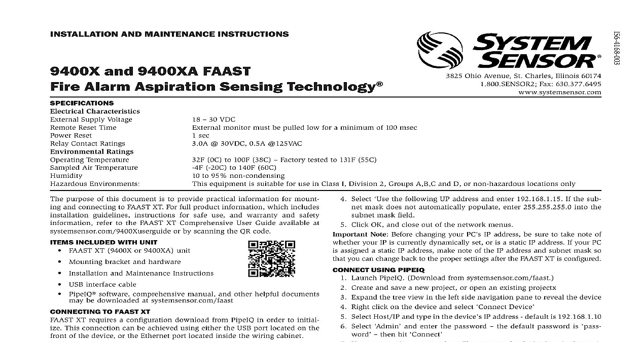
I Ohio Avenue St Charles Illinois 60174 Fax 630.377.6495 AND MAINTENANCE INSTRUCTIONS and 9400XA FAAST Alarm Aspiration Sensing Technology Characteristics Supply Voltage Reset Time Reset Contact Ratings Ratings Temperature Air Temperature Environments 30 VDC monitor must be pulled low for a minimum of 100 msec sec 30VDC 0.5A 125VAC 0C to 100F 38C Factory tested to 131F 55C 20C to 140F 60C to 95 non condensing equipment is suitable for use in Class I Division 2 Groups A B C and D or non hazardous locations only purpose of this document is to provide practical information for mount and connecting to FAAST XT For full product information which includes guidelines instructions for safe use and warranty and safety refer to the FAAST XT Comprehensive User Guide available at or by scanning the QR code INCLUDED WITH UNIT FAAST XT 9400X or 9400XA unit Mounting bracket and hardware Installation and Maintenance Instructions USB interface cable PipeIQ software comprehensive manual and other helpful documents be downloaded at systemsensor com faast TO FAAST XT XT requires a configuration download from PipeIQ in order to initial This connection can be achieved using either the USB port located on the of the device or the Ethernet port located inside the wiring cabinet TO FAAST XT VIA USB In order to connect your computer to the FAAST XT using a USB con a USB driver must first be installed The driver installation occurs the installation of PipeIQ version 2.0 or later Once the driver is in connect to the device using the following steps Launch PipeIQ Download from systemsensor com faast Create a new project and select FAAST XT device or open an existing project Expand the tree view in the left side navigation pane to reveal the device Right click on the device and select Device Select Host IP and type in the device IP address default is 192.168.1.10 Select and enter the password the default password is then click Upon connection a green dot will appear on the device icon in the navi tree TO FAAST XT VIA ETHERNET Device Configuration Address Mask Gateway DNS DNS YOUR PC PC will need to be sitting on the same local area network as the FAAST device in order to establish communication Change your PC IP address to by Accessing your network setting in your PC control panel Open Area Connection settings and select Select Protocol Version 4 TCP IPv4 and then select Select the following UP address and enter 192.168.1.15 If the sub mask does not automatically populate enter 255.255.255.0 into the mask field Click OK and close out of the network menus Note Before changing your PC IP address be sure to take note of your IP is currently dynamically set or is a static IP address If your PC assigned a static IP address make note of the IP address and subnet mask so you can change back to the proper settings after the FAAST XT is configured USING PIPEIQ Launch PipeIQ Download from systemsensor com faast Create and save a new project or open an existing projectx Expand the tree view in the left side navigation pane to reveal the device Right click on the device and select Device Select Host IP and type in the device IP address default is 192.168.1.10 Select and enter the password the default password is then hit Upon connection a green dot will appear on the device icon in the navi tree equipment must be installed in accordance with all local and national and regulations INSTALLATION pipe layout is designed using the PipeIQ software package Refer to the Instruction Manual to design the pipe network All pipe must installed in accordance with local and national codes and regulations The network should be complete before proceeding with the physical and system installation UNIT INSTALLATION sure that there are no pipes or electrical wires within the wall before any mounting holes THE MOUNTING BRACKET typical mounting location for the FAAST XT unit is on the wall The unit mounted to the wall using the enclosed mounting plate Figure 1 shows the mounting plate For easier access to the FAAST XT unit it is preferred to the mounting plate in an easily accessible location Place the mounting bracket on the wall in the desired location and use it a template to locate the necessary mounting holes Mark the hole locations and remove the bracket It is recommended to the bracket using the 3 outer mounting holes Using a drill and the proper size bit for your mounting hardware drill Use appropriate fasteners to accommodate the mounting surface and necessary holes XT device weight Secure the bracket to the wall THE DETECTOR TO THE BRACKET the mounting plate is attached the unit is ready to be mounted on to the Perform the following procedure to mount the unit Before installing the unit onto the bracket remove the appropriate con caps from the top or bottom left side of the unit to match the orien of the wiring Line up the unit with the three mounting clips and the mounting studs the left side Push the unit down onto the mounting clips and secure it with the sup washer and nut on the mounting studs protruding through the slots shown in Figure 2 1 WALL MOUNTING PLATE 2 MOUNTING SLOTS FOR MOUNTING STUDS THE AIR SAMPLING PIPE pipe network information and best practices can be found in the Installation Guide available for download at systemsensor com faast input and output ports are designed to accept nominal one inch pipe The input and output ports are tapered to provide fast easy pushfit of the sampling pipe to the unit Perform the following procedure connect the air sampling pipe to the unit Square off and de burr the end of the sampling pipe Ensure that the pipe free from any particles that might interfere with the pipe connection Remove the input plug from the input port being used either the top or Insert the air sampling pipe into the port ensuring a snug fit DO NOT of the unit these pipes PIPE device should always be exhausted in to the space that it is monitoring are some circumstances where it may be necessary to connect a pipe to exhaust port to divert the exhaust away from the location of the unit Add as little as 2ft of exhaust pipe also acts as a muffler for the fan ensuring operation The output ports are tapered the same as the input ports to fast easy push fit connection of an exhaust pipe to the unit Perform following procedure to connect the exhaust pipe to the unit Square off and de burr the end of the exhaust pipe Ensure that the pipe free from any particles that might interfere with the pipe connection Remove the plug from the exhaust port being used either the top or Insert the air exhaust pipe into the port ensuring a snug fit DO NOT of the unit these pipes working on the FAAST XT system notify all required authorities that system will be temporarily out of service Make sure all power is removed the system before opening the unit All wiring must be in accordance local codes CABLES the power ratings of the unit to determine the required wire sizes for each Use the power ratings of the connected products to determine the size USAGE electrical conduit is used for system wiring terminate the conduits at the entry ports on the top or bottom of the unit using the appropriate con connectors Run all wiring both power and alarm through the conduit and into the side of the unit enclosure as seen in Figure 3 Attach the appropriate wires to the supplied Euro connector Follow ap local codes and electrical standards for all cabling Plug the appr