System Sensor hvac high temp duct smoke detector

File Preview
Click below to download for free
Click below to download for free
File Data
| Name | system-sensor-hvac-high-temp-duct-smoke-detector-9831247056.pdf |
|---|---|
| Type | |
| Size | 1.59 MB |
| Downloads |
Text Preview
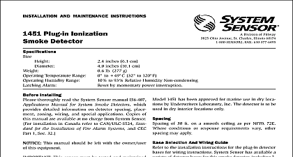
SYsTEM SENSOR Division of Pittway 3825 Ohio Avenue St Charles Illinois 60174 FAX 630 377 6495 General Description HVAC system supplies conditioned air to virtually every of a building Smoke introduced into this air duct sys will be distributed to the entire building Smoke detec designed for use in air duct systems are used to sense presence of smoke in the duct DH400 Air Duct Smoke Detectors are supplied with Sensor model 1451DH ionization detector heads model 2451 photoelectronic detector heads These two smoke detection methods are combined with an housing design that samples air passing through a and allows detection of a developing hazardous condi When sufficient smoke is sensed an alarm signal is at the fire control panel monitoring the detector appropriate action can be taken to shut off fans blow change over air handling systems etc These actions facilitate the management of toxic smoke and fire gases the areas served by the duct system detectors are designed to operate with 12 or 24 VDC listed compatible 2 wire control panels Alarm current be limited to 100mA or less by the control panel Aux relay contacts for control purposes are not available use with the DH400 Control must initiate from the con panel testing the alarm can be enabled by a magnet activated switch by insertion of a calibrated test card into the sens chamber photoelectronic version only or by the op remote test station The duct smoke detectors latch into state when alarm occurs LEDs on each detector illumi to provide local alarm indication and the optional accessory offers remote LED annunciation capability DH400 duct detector must be reset by the control panel AND MAINTENANCE INSTRUCTIONS Air Duct Smoke Detector Installing thoroughly read System Sensor Guide for Proper of Smoke Detectors in Duct Applications I56 473 XX provides detailed information on detector spacing zoning wiring and special applications Copies this manual are available from System Sensor NFPA 72 and 90A should also be referenced for de information This manual should be left with the owner user this equipment This detector must be tested and maintained following NFPA 72 requirements The detector be cleaned at least once a year of Contents General Description Exploded View of Duct Detector Components Contents of the Duct Detector Kit Limitations of Duct Detectors Installation Sequence Duct Detector Maintenance and Test Procedures Detector Cleaning Procedures Specifications Test Log Sampling Tube of Sampling Tube Gaskets Of Tables And Figures 1 Duct Detector Exploded View 2 3 Mounting Location of Speed Nuts 1 Inlet Sampling Tube Selection 4 5 Sampling Tube Mounting Configurations 6 System Wiring Diagram 2 wire 7 Wiring Diagram for Remote Test Station 8 Sampling Tube Filter Installation 9 Testing Detector Alarm 10 Detector Head Removal 11 RTS451 RTS451KEY Test Coil Installation 12 Photo Head Exploded View 13 Ion Head Exploded View 1 Manuals Online Figure 1 Exploded View Of Duct Detector Components SAMPLING TUBE cid 13 SEPARATELY STRIP HOLES DETECTOR cid 13 DETECTOR cid 13 TUBE cid 13 BASE SCREWS cid 13 ADAPTER HEAD cid 13 SEPARATELY MAGNET TUBE cid 13 Contents Of The Duct Detector Kit Complete housing base and cover assembly Two 10 sheet metal mounting screws Two sampling tube filters One test magnet Drilling template Two 5 16 inch O rings Two rubber tube bushing seals Four 6 self tapping mounting screws for the sampling One filter adapter inlet tube end plug 10 speed nuts The inlet sampling tube must be ordered sepa It must be the correct length for the width of duct where it will be installed See Table 1 on 4 to determine the inlet tube required for dif duct widths Limitations Of Duct Detectors National Fire Protection Association has established DUCT DETECTORS MUST NOT BE USED AS A SUB FOR OPEN AREA DETECTOR PROTECTION as a of providing life safety Nor are they a substitute for warning in a building regular fire detection system Sensor supports this position and strongly recom that the user read NFPA Standards 90A 72 and 101 DH400 Air Duct Smoke Detectors are listed per UL Manuals Online device will not operate without electrical power fire situations may cause an interruption of The system safeguards should be discussed with local fire protection specialist device will not sense smoke unless the ventilation sys is operating detector housing is not a weatherproof device there it should not be installed above the building roof line must be protected from the elements Installation Sequence Verify duct air flow direction and velocity Drill the mounting holes Secure the detector housing to the duct Install the sampling tube Complete the field wiring Install the filters and check pressure differential Perform detector check Install the cover Verify Duct Air Flow Direction And Velocity DH400 detectors are designed to be used in air han systems having air velocities of 500 to 4000 feet per Be sure to check engineering specifications to en that the air velocity in the duct falls within these pa If necessary an Alnor Model 6000 P velocity or equivalent may be used to check the air velocity the duct Drill The Mounting Holes the paper backing from the mounting template Affix the template to the duct at the desired location Make sure the template lies flat and on the duct Center punch holes A and B Drill the as indicated on the template Slide the two speed nuts the two small holes hole A next to the sampling tube holes hole B previously drilled in the duct See 3 Install The Inlet inlet tube shown in Figure 4 is identified by a series air inlet holes on the tube This tube must be purchased Order the correct length as specified in Table 1 width of the duct where it will be installed The exhaust is molded onto the base of the duct housing and the Exhaust Tube Extension is available as an acces in those cases where the molded exhaust port does not at least 2 inches into the duct Secure The Detector Housing To The Duct the duct housing cover Slide the foam gaskets over tube bushings as shown in Figure 2 Make sure the two holes in the gaskets line up with the two base mount holes Put one 5 16 inch O ring over each of the two sheet metal screws Use the two sheet metal screws to the detector housing to the duct CAUTION Do not the screws 2 Installation of foam gaskets over sampling bushings SAMPLING BUSHING DETECTOR TUBE BUSHING GASKETS inlet tube is always installed in the centermost housing with the air inlet holes facing into the air flow To proper installation the tube mounting flange is with arrows Make sure the inlet tube is mounted that the arrows point into the air flow Figure 5 shows various combinations of tube mounting configurations respect to air flow Mounting the detector housing in a orientation is acceptable provided that the air directly into the sampling tube holes as indicated in 4 1 Inlet tubes required for different duct Duct Width Tube Required to 2 ft to 4 ft to 8 ft to 12 ft HOLES FOR ATTACHING HOUSING TO DUCT 3 Speed nut mounting location B A Manuals Online 4 Air duct detector inlet sampling tube HOLES FLOW FACE AIR FLOW FLOW DIRECTION 5 T