System Sensor i3 Series Thermal Detectors Manual

File Preview
Click below to download for free
Click below to download for free
File Data
| Name | system-sensor-i3-series-thermal-detectors-manual-3470861529.pdf |
|---|---|
| Type | |
| Size | 903.45 KB |
| Downloads |
Text Preview
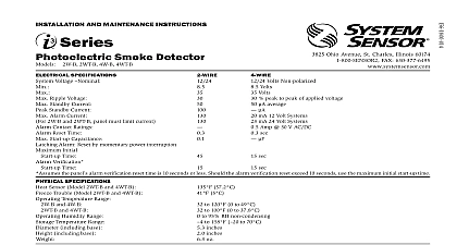
I AND MAINTENANCE INSTRUCTIONS Smoke Detector Ohio Avenue St Charles Illinois 60174 FAX 630 377 6495 peak to peak of applied voltage average Form C Relay 2WTA B Sounder Form C Relay 4WTA B Sounder Form C Relay Sounder 4WITAR B Isolated Thermal Form C Relay Sounder for 2WTR B and 4WTR B SPECIFICATIONS Voltage Min Max Ripple Voltage Standby Current Standby Current Alarm Current 4WTA B 4WTR B 4WTAR B 4WITAR B 2WTR B 2WTA B Contact Ratings C Contact Ratings Signal temp 3 tone Annunciator Output Relay Time min Start up Capacitance Initial Start up Time Start up Time Direct Power Non reverse Polarity 130 mA limited by panel Polarity Power 30 mA for the 2WTA B in alarm 12 mA for all other 2WTA B units on the loop Add 25 mA for the RRS MOD reversing relay alarm current Assumes the panel alarm verification reset time is 10 seconds or less Should the alarm verification reset exceed 10 seconds use the maximum initial start up time min in alarm or supply polarity reversed Sounder units only maximum panel must limit current 30 V AC DC 30 V AC DC SPECIFICATIONS Sensor Trouble Temperature Range Humidity Range Temperature Range including base including base 57.2 5 to 100 0 to 37.8 to 95 RH non condensing to 158 to 70 inches inches oz INSTALLING read thoroughly System Sensor Applications Guide for System Smoke SPAG91 which provides detailed information on detector spacing zoning wiring and special applications This is available online System Sensor web site www systemsensor com This manual shall be left with the owner user of this equipment This detector must be tested and maintained regularly follow National Fire Protection Association NFPA 72 National Fire Alarm Code At a minimum cleaning should be performed annually DESCRIPTION 2WTR B and 2WTA B are 2 wire photoelectric smoke detectors models 4WTA B 4WTAR B and 4WITAR B are 4 wire photoelectric smoke All models incorporate a state of the art optical sensing chamber an advanced microprocessor The microprocessor allows the detector to adjust its sensitivity back to the factory setting when it becomes sensitive due to contaminants settling in its chamber In order for this to work properly the chamber must never be opened while power is to the smoke detector This includes cleaning maintenance or screen All models also feature a restorable built in fixed temperature thermal detector and are also capable of sensing a freeze condition if temperature is below 41 2WTA B 4WTA B 4WTAR B and 4WITAR B contain a piezoelectric which generates the ANSI S3.41 temporal pattern in an alarm condition detectors on a zone will sound when the power supply to them is reversed RRS MOD can be used for the power supply reversal function The RRS also enables all the detectors sounders on a zone to be synchronized allows the zone to be silenced from the panel by entering the alarm si key at the keypad detector that initiated the alarm condition will have its red LED and Form relays if applicable latched until reset by panel model 4WITAR B photoelectronic smoke sensor is isolated from the fixed heat sensor providing a self resetting local audible smoke alarm does not alarm at the panel Only the fixed temperature heat sensor will the 4WITAR B to initiate an alarm at the panel and the relay to change state In order for all i3 sounder detectors on a loop to sound when the panel the supply voltage polarity must be reversed A reversing relay System model number RRS MOD must be used The RRS MOD is designed allow all i3 Series detectors in the same loop to sound when one of the goes into alarm In addition the RRS MOD will synchronize all of i3 Series sounder smoke detectors on the loop Some panels may require use of programmable outputs Refer to System Sensor literature for further on the RRS MOD i3 Series detectors are designed to provide open area protection Two wire models be used with compatible UL Listed panels only used with an Ready control panel or the i3 Series 2W MOD2 mod refer to installation manual the 2WTR B and 2WTA B are capable of a needed signal The 2W MOD2 can indicate a need cleaning replacement or a freeze trouble at the control panel or module 2W MOD2 has replaced the previous model number 2W MOD To ensure remote maintenance signaling capabilities do not use the 2W MOD i3 model numbers 2WTR B and 2WTA B of the 2WTR B 2WTA B 4WTR B 4WTA B 4WTAR B and detectors is simplified by the use of a mounting base that may pre wired to the system allowing the detector to be easily installed or re The mounting base installation is further simplified by the incorpora of features compatible with drywall fasteners LEDs on the detector provide a local visual indication of the detector status 1 DETECTOR LED MODES standby of sensitivity Trouble LED 10 sec 5 sec LED 10 sec 5 sec 10 sec an initial power up delay the red and green LEDs will blink synchro once every ten seconds It will take approximately 80 seconds for the to finish the power up cycle see Table 2 2 POWER UP SEQUENCE FOR LED STATUS INDICATION LED Status Indication LED Status Indication seconds minutes excessive electrical noise is present to Electrical Specifications for start up time in conjunction with panel verification If during power up the detector determines there is excessive electri noise in the system such as those caused by improper grounding of the or the conduit both LEDs will blink for up to 4 minutes before display detector status see Table 2 power up has completed and the detector is functioning normally within listed sensitivity range the green LED blinks once every five seconds If the is in need of maintenance because its sensitivity has shifted outside listed limits the red LED blinks once every five seconds When the detec is in the alarm mode the red LED latches on The LED indication must not used in lieu of the tests specified under Testing In a freeze trouble condi the red LED will blink once every 10 seconds refer to Table 1 measure the detector sensitivity the i3 Series Model SENS RDR Infrared Reader tool see Figure 4 should be used Refer to instructions D100 98 00 for the proper use of the SENS RDR 2WTR B and 2WTA B also include an output that allows an optional RA400Z RA100Z Remote Annunciator to be connected spacing guidelines are 30 with each detector covering 900 ft2 maximum conditions NFPA 72 the local Authority Having Jurisdiction AHJ and or ap codes for specific information regarding the spacing and placement smoke detectors i3 Series detector is supplied with a mounting base that can be ceiling or To a single gang box or To a 31 or 4 inch octagonal box or To a 4 inch square box with a plaster ring or Direct mount or to ceiling using drywall fasteners 1 MOUNTING OF DETECTOR i3 Series heads and bases are keyed so that all heads will only fit into respective bases One model 4 wire relay base will accept the 4WTR B and 4WITAR B detector heads and no others The 2WTR B 2WTA B 4WTA B will only fit into their respective mounting bases and no others heads and bases are clearly identified as either 2 wire or 4 wire When the i3 Series ensure that the head is mounted to the correct base the test switch is aligned with the tamper release tab FEATURE i3 Series detectors include a tamper resistant feature that prevents re from the