System Sensor i4 Series Modules Manual

File Preview
Click below to download for free
Click below to download for free
File Data
| Name | system-sensor-i4-series-modules-manual-2561097438.pdf |
|---|---|
| Type | |
| Size | 1.84 MB |
| Downloads |
Text Preview
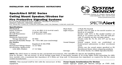
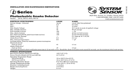
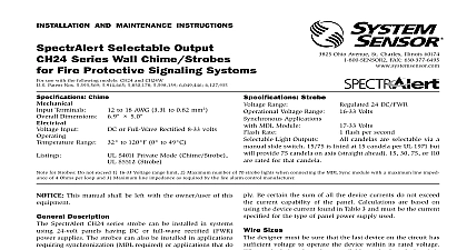
INSTALLATION AND MAINTENANCE INSTRUCTIONS Series Interface Module and COSMOD4W use with COSMO 2W and COSMO 4W detectors Specifications Supply Voltage Power up Time Current Current Contact Rating Contact Rating IDC Loop Wiring Resistance Inputs Power Out Reset Time Communication Cycle Walk Test Availability Specifications Temperature Range Humidity Range Temperature Range Weight Gauge Acceptance Compatibility Requirements Loop Voltage Loop Voltage Loop Resistance Loop Ripple Loading Capacitance Alarm Current Reset Voltage Delay Alarm Reset Time Normal Load Current Type Device Style Zone Identifier Zone Identifier Detectors Per Zone INSTALLATION information is included as a quick reference installation guide Refer to control panel installation manual for detailed system information If the will be installed in an existing operational system inform the operator local authority that the system will be temporarily out of service Discon power to the control panel before installing the module 50 C 32 122 F 95 RH 70 C 4 158 F inches inches inches lbs 22 AWG Max 14 AWG This manual should be left with the owner user of this equipment product is intended for use in ordinary indoor locations DESCRIPTION i4 series module is designed to interface between compatible i4 series CO smoke detectors Model COSMO 2W and COSMO 4W and security fire panels It can also be used to retrofit compatible i4 detectors into an existing loop of i3 smoke detector models 2WTA B or without adding wires The module interprets signals and translates into a separate smoke zone and a separate CO zone each with alarm trouble signals The module will interconnect the detectors connected to and alarm them in either Temporal 3 or Temporal 4 pattern Optional trig are provided to initiate multiple modules to sound an additional RSS Ohio Avenue St Charles Illinois 60174 FAX 630 377 6583 power 2 Wire Min 8.5 Volts DC Power limited Max 35 Volts DC Power limited Min 10 Volts DC Power limited Max 35Volts DC Power limited milliseconds 61mA max 45mA 12V In 26mA 24V In 4 Wire 52mA max 37mA 12V In 22mA 24V In not include current draw from attached detectors or EOL relay 181mA max 121mA 12V In 64mA 24V In 4 Wire 78mA max 57mA 12V In 34mA 24V In not include reverse polarity current draw from attached detectors mA 36 Volts DC resistive 25 ohms mA 36 Volts DC resistive 25 ohms 50 Ohms 4 Wire 300 Ohms On Voltage 1.5V Max On Voltage Vin Voltage as Input Power Unregulated limited to 250mA milliseconds minutes minutes after power up or panel reset Volts DC Volts DC Ohms mVpp mF mA Volts DC seconds mA Ohms 5 and D 2 wire i4 series model COSMO 2W and or i3 series model 2WTA B detectors is not required Local status indication is provided by 4 LED and a 3 DIP switch enables user configuration i4 COSMOD2W 2 wire interface module offers additional functionality Ability to query for a for maintenance condition from 2 wire i4 model COSMO 2W and i3 series model 2WTA B smoke detectors One relay is available to indicate a multitude of maintenance conditions the control panel All conditions are displayed at the module and at the detector EZ Walk test mode allows the installer to easily verify that all detectors a loop are operational Allows 2 wire smoke detectors to be used on any compatible 4 wire panel and provides Style D Class A wiring on the detector loop Compatible with System Sensor i4 series combination CO smoke detectors System Sensor i3 Series smoke detectors models 2WTA B or 4WTA B Allows up to 12 compatible devices including the i4 series combination detector to be integrated with a panel Activates sounders of all detectors on loop in either Temporal 3 or 4 pattern ANNUNCIATON i4 series interface module has four visible LED The green LED is a su LED it blinks during power on reset and during normal operation yellow LED is used to indicate a loop wiring fault and will blink when it in EZ Walk test mode The red LED signals smoke events it blinks during maintenance events and lights constantly during smoke alarm events blue LED signals CO events it blinks during CO trouble or CO end of life lights constantly during CO alarm 1 MODULE FRONT VIEW LED LED LED LED Walk Test Switch only LED LED 1 OPERATION MODES standby 1 Sec power wiring fault 1 Sec Walk Test Mode only 1 Sec 5 Sec Smoke CO 1 Sec 1 Sec Smoke CO Blink 1 Sec only Trouble only 1 Sec 5 Sec 1 Sec 10 Sec 5 Sec 1 Sec Trouble STANDBY module is powered and detectors on the loop are operating normally POWER NON OPERATIONAL is not applied to the module or communication between the module the detectors on the loop is unsuccessful WIRING FAULT an open circuit occurs on the loop the module will indicate the condition by the yellow LED 2 wire units will then power the Style D Class A When the wiring issue on the loop has been resolved the module turn the yellow LED off WALK TEST MODE indicates the module and detectors are in EZ Walk Test Mode See Walk section for instructions on how to initiate and perform the EZ Walk test SMOKE ALARM CO ALARM SMOKE CO smoke alarm will be indicated by the red LED A CO alarm will be indicated the blue LED smoke alarm is not self restoring Once a smoke alarm has been signaled red LED will illuminate until the module is reset by removal of power CO alarm is self clearing Once a CO alarm has been signaled the blue LED illuminate Once the initiating device ceases to signal the CO event the LED will turn off If a CO alarm is signaled and not cleared prior to a alarm condition the module will keep both the blue and red LED If a smoke alarm is signaled first the module will not be able to notification of a CO alarm condition and will not be able to report it the panel condition means one or more detectors on the loop have a smoke main issue See Maintenance Inquiry section for further details TROUBLE condition means one or more detectors on the loop are measuring the temperature is near the freezing point See Trouble Inquiry for further details TROUBLE module can be notified of a detector with a CO trouble condition All CO conditions will be reported on the CO zone and displayed with a blink blue LED The module is not able to determine the number of detectors have a CO trouble condition or which trouble condition exists module can be mounted to a 4 11 16 inch back box or inside a listed dedi enclosure When mounting inside an enclosure with pre stamped holes may be easier to align the bottom screw hole first It is not necessary to use module cover when mounting inside an enclosure 2 MOUNTING FOR MOUNTING VISTA ENCLOSURE 6x3 4 Type AB FOR MOUNTING VISTA ENCLOSURE 6x5 16Type AB or Type F FOR MOUNTING 4 11 16 JUNCTION BOX GUIDELINES All wiring must be installed in compliance with the NFPA 70 standards Na Electrical Code applicable state and local codes and any special re at the local Authority Having Jurisdiction AHJ screw terminals in the mounting base will accept 14 22 gauge wire Wire are made by stripping approximately of insulation from the of the feed wire inserting it into the proper base terminal and tightening screw to secure the wire in place Do not put wires more than 2 gauge under the same clamping plate