System Sensor KBS and KMS Models

File Preview
Click below to download for free
Click below to download for free
File Data
| Name | system-sensor-kbs-and-kms-models-8234659710.pdf |
|---|---|
| Type | |
| Size | 620.06 KB |
| Downloads |
Text Preview
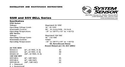
KMS KBS BELL SERIES INSTRUCTIONS Read Carefully and Save instruction manual contains important information about the installation and operation of bells Purchasers who bells for use by others must leave this manual or a copy of it with the user Sensor supplies bells for nearly all sprinkler fire alarm burglar applications instructions apply to all System Sensor bells in the series Read all instructions carefully before beginning Follow those instructions that apply to the model you are installing NOT USE IN POTENTIALLY EXPLOSIVE ATMOSPHERES NOT LEAVE ANY UNUSED WIRES EXPOSED DESCRIPTION National Fire Protection Association has published codes standards and recommended practices for the installa and use of the above appliances It is recommended that the installer be familiar with these requirements with local and any special requirements of the authority having jurisdiction bells are intended to be connected to alarm indicating circuits of UL listed fire alarm control panels Terminal con are polarized to enable supervision of the installation wiring The KMS bells require 24 VDC and the KBS bells 120 VAC installing any alarm device be thoroughly familiar with 72 13 13A Maintenance and Use of Protective Signaling Systems of Sprinkler Systems Testing and Maintenance of Sprinkler Systems specifically Chapters 4 and 5 applicable NFPA standards local codes and the requirements of the authority having jurisdiction to follow these directions may result in failure of the device to report an alarm condition System Sensor is not for devices that have been improperly installed tested or maintained voltage Electrocution Hazard Do not handle live AC wiring or work on a device to which AC power is applied so may result in severe injury or death Do not loop wire under terminals Break wire runs to provide supervision of connections Remove the gong Wire the bell in the circuit See Figure 1 Note polarity markings on bells Terminals on bells are designed to accept 14 GA wire When using a 10 or 12 GA wire use Panduit terminal or equivalent for connection of power leads Sensor 3825 Ohio Avenue St Charles Illinois 60174 1 800 SENSOR2 FAX 708 377 6495 Mount bell mechanism on 4 square electrical box with the striker facing down See Figures 2 5 Replace the gong The top of the bell must be mounted a minimum of 90 above the floor or within 6 of the ceiling VDC FROM ALARM RESISTOR PANEL BELL BELL NOT LOOP WIRE UNDER TERMINALS BREAK WIRE RUN TO PROVIDE SUPERVISION CONNECTIONS ARE SHOWN IN ALARM KBS 120 VAC powered bells per control panel manufacturer instructions 1 Typical KMS Bell Wiring Diagram shown in alarm condition MECHANISM AND GONGS INSTALLATION SQUARE BOX INCLUDED LOCATED ON BOTTOM BELL VISIBLE FROM REAR BELL SQUARE HOLE PATTERN ARE LOCATED TO MOUNT TO A 4 SQUARE OUTLET BOX 2 3 INSTALLATION CONDUIT INSTALLATION BOX INCLUDED SQUARE BACK NOT INCLUDED NO WBBF BELL BELL PLATE INCLUDED NO P40 86 03 4 5 RATING dBA at 10 ft Spherical Sound Measurement level measurements are made in accordance with UL Standard 464 The sound power output is measured in a room Bell shall be capable of providing a sound output equivalent to not less than 75 dBA Measurement level in the indoor installation may vary depending upon the placement spacing and type of walls etc Series Voltage Series Voltage VDC Nominal VDC Minimum VDC Maximum ma VAC ma VDC KMS VAC KBS Polarized 24 VDC P 24 VDC P 24 VDC P 120 VAC P 120 VAC P 120 VAC P TESTING Output UL 464 Field Output at 10 notify a central station monitoring the system before repairing maintaining or testing alarm devices completion of initial installation all bells shall be tested per NFPA 72G Periodic testing should be performed at annually Test more often if required by the authority having jurisdiction Under normal conditions System Sensor should provide years of trouble free service however after extended service parts of the bell may become worn this case bell should be replaced not repair or replace any bell components in the field If bell does not perform properly replace the entire Failure to follow this instruction may result in failure of the bell to report an alarm condition Sensor bells are designed to provide fire and security hazard warning OF ALARM DEVICES Bells may not work or operate properly if sprinkler piping being monitored is plugged with pipe scale mud stones or foreign material Sprinkler systems should be checked regularly for such blocking material following the instruc in Chapter 5 of NFPA Standard 13A BELLS WILL NOT WORK WITHOUT POWER Since the bell gets its power from the fire or security panel monitoring alarm system if power is cut for any reason the device will not provide the desired audible warning Alarms gen by the activation of waterflow detectors may not be received by a central station if telephone or other commu lines to the detector are out of service disabled or open BELLS MAY NOT BE HEARD The loudness of the alarm device meets or exceeds current Underwriters Laboratories However the bell may not alert a sound sleeper or one who has recently used drugs or has been drinking beverages The sounding device may not be heard on a different floor from the person in hazard or if placed far away to be heard over the ambient noise such as traffic air conditioners machinery or music appliances that prevent alert persons from hearing the alarm THE SOUNDER MAY NOT BE HEARD BY PERSONS WHO ARE IMPAIRED Sprinkler systems and associated bells are not a substitute for insurance Building owners should always insure prop and lives being protected by sprinkler systems If valves controlling the water supply to a sprinkler system are closed vane type waterflow detectors will not work and will not sound All valves controlling a sprinkler water supply should be sealed or locked in the normally open The normally open position should be monitored by a sprinkler supervisory switch YEAR LIMITED WARRANTY Sensor warrants its enclosed KMS or KBS bell to be free from defects in materials and workmanship under nor use and service for a period of three years from date of manufacture System Sensor makes no other express war for this piece of equipment No agent representative dealer or employee of the Company has the authority to or alter the obligations or limitations of this Warranty The Company obligation of this Warranty shall be limit to the repair or replacement of any part of the bell which is found to be defective in materials or workmanship under use and service during the three year period commencing with the date of manufacture After phoning System toll free number 800 SENSOR2 736 7672 for a Return Authorization number send defective units postage to Sensor Department Ohio Avenue Charles IL 60174 include a note describing the malfunction and suspected cause of failure The Company shall not be obligated repair or replace units which are found to be defective because of damage unreasonable use modifications or alter occurring after the date of manufacture In no case shall the Company be liable for any consequential or incidental for breach of this or any other Warranty expressed or implied whatsoever even if the loss or damage is caused the Company negligence or fault Some states do not allow the exclusion or limitation of incidental or consequen damages so the above limitation or exclusion may not apply to you This Warranty gives you specific legal rights you may also have other rights which vary from state to state System Sensor 1993