System Sensor L-Series Horns and Chimes - Wall (I56-5844)

File Preview
Click below to download for free
Click below to download for free
File Data
| Name | system-sensor-l-series-horns-and-chimes-wall-i56-5844-2613450879.pdf |
|---|---|
| Type | |
| Size | 2.53 MB |
| Downloads |
Text Preview
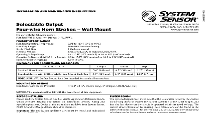
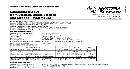
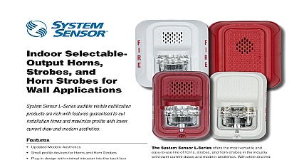
INSTALLATION AND MAINTENANCE INSTRUCTIONS Output and Chimes Wall Mount use with the following models HRL HWL Horns HGRL HGWL CHRL CHWL SPECIFICATIONS Operating Temperature Range Voltage Voltage Range includes fire alarm panels with built in sync Voltage with MDL3 Sync Module terminal wire gauge Ohio Avenue St Charles Illinois 60174 FAX 630 377 6495 to 120 0 to 49 to 93 Non condensing 12VDC or regulated 24DC FWR to 17.5V 12V nominal or 16 to 33V 24V nominal to 17.5V 12V nominal or 16.5 to 33V 24V nominal to 18 AWG FOR PRODUCTS AND ACCESSORIES MOUNTING BOX OPTIONS PRODUCTS and Chime Horn Horn 143mm 133 119mm 32mm 88 mm 32 mm x 4 x 1 Single Gang Gang 4 Octagon Gang 149 mm with SBBRL WL Mount Back Box Horn with SBBGRL WL Mount Back Box SBBRL WL Surface Mount Back Box intended only for standard horns and chimes Surface Mount Back Box intended for compact horns This manual shall be left with the owner user of this equipment 94.5 mm 125 mm 140.5 47 mm 39 mm INSTALLING read the System Sensor Audible Visible Application Reference Guide provides detailed information on notification devices wiring and applications Copies of this manual are available from System Sensor 72 and NEMA guidelines should be observed The notification appliance used must be tested and maintained NFPA 72 requirements DESCRIPTION Sensor series of notification appliances offer a wide range of audible for life safety notification Our horns and chimes come with 10 field tone and volume combinations for a wide range of systems Horns in two attractive mounting designs standard and compact They are for indoor applications and approved for wall and ceiling mount are public mode notification appliances intended to alert occupants of life safety event Chimes are private mode notification appliances used to trained personnel to investigate possible emergency situations and take action Both the horn and the chime are listed to ANSI UL 464 Sensor notification appliances are designed to be used in 12 VDC or 24V FWR full wave rectified systems System Sensor AV devices be activated by a compatible fire alarm control panel or power supply power from these supplies can be either regulated or coded pulsing supplies Refer to the appropriate fire alarm control panel manufacturer power supply for more information Sensor wall horns and chimes are electrically backward compatible the previous generation since 1996 of notification appliances They enabled with System Sensor synchronization protocol which requires to a power supply capable of generating the System Sensor pulses a FACP NAC output configured to System Sensor protocol or the use of MDL 3 module to generate the syn protocol ALARM SYSTEM CONSIDERATIONS National Fire Alarm and Signaling Code NFPA 72 requires that all au notification appliances used for building evacuation installed after July 1996 produce temporal coded signals Signals other than those used for purposes do not have to produce the temporal coded signal Sys Sensor recommends spacing notification appliances in compliance with 72 DESIGN system designer must make sure that the total current draw by the devices the loop does not exceed the current capability of the panel supply and the last device on the circuit is operated within its rated voltage The draw information for making these calculations can be found in the within the manual For convenience and accuracy use the voltage drop on the System Sensor website www systemsensor com calculating the voltage available to the last device it is necessary to the voltage due to the resistance of the wire The thicker the wire the the voltage drop Wire resistance tables can be obtained from electri handbooks Note that if Class A wiring is installed the wire length may up to twice as long as it would be for circuits that are not fault tolerant total number of strobes on a single NAC must not exceed 69 for 24 volt TONES Sensor offers a wide variety of horn and chime tones for your life needs including temporal 3 pattern 1 2 second on 1 2 second off second on 1 2 second off 1 2 second on 1 1 2 off and repeat which is by ANSI and NFPA 72 for standard emergency evacuation signaling the horn and chime are compatible with coded power supplies Coded supplies power the NAC and all connected AV devices with certain pattern that can be programmed from such power supplies In this there is no delay in device operations after the power is applied the will stop after the power is removed select the tone turn the rotary switch on the back of the product to the setting See Figure 1 1 AUDIO SETTINGS 4 HORN SOUND OUTPUT dBA Volts horn settings can be found in Table 1 Available chime settings can found in Table 2 Tones listed as coded are intended to be used with coded supplies 1 HORN TONES Setting 5 CHIME CURRENT DRAW mA Volts KHz Temporal KHz Temporal KHz Non Temporal KHz Non Temporal KHz Coded second chime second chime second chime second chime 3 chime 3 chime second whoop second whoop chime coded TO BE USED second chime second chime second chime second chime 3 chime 3 chime second whoop second whoop chime coded TO BE USED KHz Temporal KHz Temporal KHz Non Temporal KHz Non Temporal KHz Coded second chime second chime second chime second chime Chime chime second whoop second whoop chime coded TO BE USED 2 CHIME TONES 6 CHIME SOUND OUTPUT dBA Setting Volts DRAW AND AUDIBILITY RATINGS the horn the current draw for each setting is listed in Table 3 and the ratings can be found in Table 4 For chime the current draw for setting is listed in Table 5 and the audibility ratings can be found in Table Tones listed as coded are intended to be used with coded power supplies 3 HORN CURRENT DRAW mA Volts KHz Temporal KHz Temporal KHz Non Temporal KHz Non Temporal KHz Coded AND MOUNTING wiring must be installed in compliance with the National Electric Code the local codes as well as the authority having jurisdiction Wiring must be of such length or wire size which would cause the notification appli to operate outside of its published specifications Improper connections prevent the system from alerting occupants in the event of an emergency sizes up to 12 AWG 2.5 mm may be used with the mounting plate The plate ships with the terminals set for 12 AWG wiring wire connections by stripping about 3 8 of insulation fro