System Sensor L-Series Low Frequency Sounder Strobes Manual

File Preview
Click below to download for free
Click below to download for free
File Data
| Name | system-sensor-l-series-low-frequency-sounder-strobes-manual-7961428503.pdf |
|---|---|
| Type | |
| Size | 3.07 MB |
| Downloads |
Text Preview
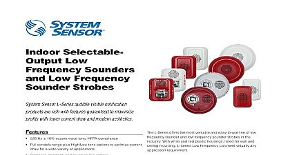
INSTALLATION AND MAINTENANCE INSTRUCTIONS Low Frequency Strobes and Sounder Strobes Ohio Avenue St Charles Illinois 60174 FAX 630 377 6495 use with the following models P2RL LF P2WL LF HRL LF HWL LF HGRL LF HGWL LF HCRL LF HCWL LF PC2RL LF PC2WL LF SPECIFICATIONS Temperature Range Flash Rate Voltage Low Frequency Sounder Voltage Low Frequency Sounder Strobe Voltage Range includes fire alarm panels with built in sync Voltage with MDL3 Sync Module terminal wire gauge to 120 0 to 49 to 93 Non condensing flash per second 24VDC FWR 24VDC FWR to 33V 24V nominal to 33V 24V nominal to 18 AWG FOR PRODUCTS AND ACCESSORIES PRODUCTS Sounder Strobe Sounder 143mm 119mm 38 mm 143mm 133 mm 119mm 88 mm 49mm 38 mm device with SBBRL WL Surface Mount Back Box 145 mm 84mm device with SBBGRL WL Surface Mount Back Box SBBRL WL Surface Mount Back Box intended only for standard sounder and sounder strobe SBBGRL WL Surface Back Box intended for compact sounder 137 mm 76mm PRODUCTS Strobe 173.5mm 36mm 173.5mm 62.7mm with SBBCRL WL Surface Mount Back Box 175.8mm 99mm BOX OPTIONS x 4 x 1 Single Gang Double Gang 4 Octagon SBBRL WL wall SBBCRL WL ceiling Indoor Products Indoor Products Gang SBBGRL WL wall This manual shall be left with the owner user of this equipment DESCRIPTION L Series low frequency series of notification appliances offers a range low frequency sounder and low frequency sounder strobe products for and ceiling applications Studies have shown that low frequency audible that operate around 520Hz are more effective in waking individuals sleeping areas These products are electrically backward compatible with previous generation of SpectrAlert Advance notification appliances The products fit systems where a single NAC controls both sounder and The System Sensor MDL3 module may be used to provide synchroni for strobes and sounder strobes configured for Temp 3 tone models are approved for wall and ceiling installations ALARM SYSTEM CONSIDERATIONS National Fire Alarm Code NFPA 72 requires that all sounders used for evacuation produce temporal coded signals Signals other than those for evacuation purposes do not have to produce the temporal coded sig The National Fire Alarm Code NFPA 72 requires that audible appliances in sleeping areas produce a low frequency alarm signal that shall a square wave or provide equivalent awakening ability effective Jan 1 System Sensor recommends spacing notification appliances in compli with NFPA 72 DESIGN AND WIRING system designer must make sure that the total current drawn by the de on the loop does not exceed the current capability of the panel supply that the last device on the circuit is operated within its rated voltage The draw information for making these calculations can be found in the within this manual For convenience and accuracy use the voltage drop on the Tools menu of the System Sensor website calculating the voltage available to the last device it is necessary to the voltage drop due to the resistance of the wire The thicker the the smaller the voltage drop Wire resistance tables can be obtained electrical handbooks Note that if Class A wiring is installed the wire may be up to twice as long as it would be for circuits that are not fault The total number of strobes on a single NAC must not exceed 69 for volt applications Loop resistance on a single NAC should not exceed 120 for 24 volt A shorting spring is provided between terminals 2 and 3 of the mount plate to enable wiring checks after the system has been wired but prior installation of the final product This spring will automatically disengage the product is installed to enable supervision of the final system of a notification device will result in an open circuit indication on NAC 3 ATTACH MOUNTING PLATE TO BACK BOX WALL MOUNT BOX WALL MOUNT BACK BOX CEILING MOUNT BOX CEILING MOUNT BACK BOX COMPACT WALL MOUNT BOX COMPACT WALL MOUNT BACK BOX 4 ATTACH DEVICE ONTO MOUNTING PLATE WALL MOUNT SOUNDER WITH SURFACE MOUNT BACKBOX Attach mounting plate to junction box See Figures 3A 3C and 3E AND REMOVING APPLIANCE Connect field wiring to terminals See Figures 1 and 2 If the product is not to be installed at this point use the paint cover to contamination of the mounting plate To attach product to mounting plate a Remove the protective dust cover b Hook the tabs on the top of the product housing into the grooves on plate c Pivot the product into position to engage the terminals on the mount plate Make sure that the tabs on the back of the product housing engage with the mounting plate d Hold product in place with one hand and secure product by tighten the single mounting screw in the front of the product housing To remove products from the mounting plate press the locking button loosening the captivate mounting screw Ceiling models only A SURFACE MOUNT BACK BOX The surface mount back box may be secured directly to the wall or ceil Use of grounding bracket with ground screw is optional See Figures 3D 3F and 4 The wall mount box must be mounted with the up arrow pointing up Figure 6 Threaded knockout holes are provided for the sides of the box for inch inch conduit adapter Knockout plugs in the back of the box can used for inch and inch rear entry To remove the inch or inch knockout place the blade of a flat head along the outer edge and work your way around the knock as you strike the screwdriver See Figure 7 NOTE Use caution not to strike the knockout near the top edge of the mount back box V500 and V700 wiremold raceways are also provided Use V500 for low applications and V700 for high profile applications To remove the knockout turn pliers up See Figure 7 Attach the mounting plate to the surface mount back box using the four screws See Figures 3B 3D 3F and 4 To wire and attach the product follow steps 4 and 5 of and Appliance above 1 WIRING DIAGRAM EOL TERMINALS Negative Line in and out Positive Line in and out Positive Line in and out Guide A0475 01 2 WIRING TERMINALS SHORTING SPRING AND STRIP GUIDE Spring A0579 00 1A WALL SOUNDER STROBE CURRENT DRAW mA AND SOUND OUTPUT dBA draw mA VDC FWR 1B CEILING SOUNDER STROBE CURRENT DRAW mA AND SOUND OUTPUT dBA draw mA VDC FWR 3 3 4 4 3 3 4 4