System Sensor L-Series Speakers - Wall and Ceiling (I56-0001)

File Preview
Click below to download for free
Click below to download for free
File Data
| Name | system-sensor-l-series-speakers-wall-and-ceiling-i56-0001-6709124385.pdf |
|---|---|
| Type | |
| Size | 6.03 MB |
| Downloads |
Text Preview
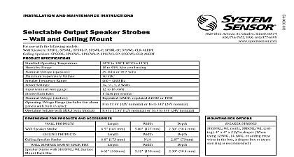
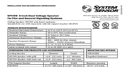
INSTALLATION AND MAINTENANCE INSTRUCTIONS Voltage Speakers Fire and ECS MNS Systems Wall and Ceiling Mount Ohio Avenue St Charles Illinois 60174 FAX 630 377 6495 Speaker 165 mm 127 mm 24.6 mm Speaker 173 mm 25.4mm BOX OPTIONS wall SBBCRL SBBCWL 4 x 4 x 21 8 or deeper using 12AWG 14 AWG or adding extra in the box a deeper box or extension is recommended use with the following models Speakers SPRL SPWL Speakers SPCRL SPCWL SPECIFICATIONS Operating Temperature Range Voltage Supervisory Voltage Frequency Range Settings terminal wire gauge DIMENSIONS PRODUCTS PRODUCTS to 120 0 to 49 to 93 Non condensing Volts or 70.7 Volts VDC 4000 Hz 1 2 Watts to 18 AWG This manual shall be left with the owner user of this equipment INSTALLING read the System Sensor Voice Evacuation Application Guide which detailed information on speaker notification devices wiring and applications Copies of this manual are available from System Sensor 72 and NEMA guidelines should be observed The notification appliance used must be tested and maintained NFPA 72 requirements DESCRIPTION Sensor series of notification appliances offer a wide range of audible visible devices for life safety notification Our line of speakers is designed be used at either 25 or 70.7 volts and operate at any one of four input levels Our speakers are suitable for dry and damp environments products are electrically backwards compatible with previous genera of System Sensor speakers With its low total harmonic distortion the Sensor SPL series offers high fidelity sound output Wall and ceiling may be used interchangeably wall products may be used on ceiling ceiling product may be used on wall speakers and all power level settings are listed to ANSI UL 1480 require for public mode applications ALARM SYSTEM CONSIDERATIONS wiring must be installed in compliance with the National Electrical Code and applicable local codes System Sensor recommends installing fire speakers in compliance with NFPA 72 ANSI UL 1480 and NEC 760 AND MOUNTING wiring must be installed in compliance with the National Electric Code the local codes as well as the authority having jurisdiction Wiring must be of such length or wire size which would cause the notification appli to operate outside of its published specifications Improper connections prevent the system from alerting occupants in the event of an emergency sizes up to 12 AWG 2.5 mm may be used with the mounting plate The plate ships with the terminals set for 12 AWG wiring wire connections by stripping about 3 8 of insulation from the end of wire Then slide the bare end of the wire under the appropriate clamping and tighten the clamping plate screw Figure 1 for wiring terminals and strip guide reference Connect the speaker See Figure 1 There are two rotary switches on the back of the product The first switch used to select either 25 or 70.7 volts input and the second switch is used to the input power of 1 or 2 watts See Figure 2 1 WIRING DIAGRAM AND WIRING TERMINALS from Terminals Negative Line in and out Positive Line in and out Positive Line in and out to Device or EOL Do not loop electrical wiring Wires the device to the control must be broken at the device electrical supervision order 2 SPEAKER WATTAGE AND VOLTAGE SETTINGS AND REMOVING APPLIANCE Attach mounting plate to junction box See Figures 4 and 5 Connect field wiring to terminals See Figure 1 If the product is not to be installed at this point use the protective dust to prevent contamination of the wiring terminals on the mounting plate To attach product to mounting plate Remove the protective dust cover Hook the tabs on the top of the product housing into the grooves on mount plate Pivot the product into position to engage the terminals on the mounting Make sure that the tabs on the back of the product housing fully en with the mounting plate Hold product in place with one hand and secure product by tightening the mounting screw in the front of the product housing Models only To remove product from the mounting plate loosen the mounting screw and press the locking button in place snaps are not intended to secure the product to the back The product must be secured to the back box using the screws provided finish should not be altered Do not paint Reverberant dBA 10 ft Anechoic dBA 10 ft not over tighten mounting plate screws this may cause mounting plate flex 4 WALL SPEAKER SPRING FEATURE Sensor notification appliances come with a shorting spring that is pro between terminals 2 and 3 of the mounting plate to enable system con checks after the system has been wired but prior to installation of the product See Figure 3 This spring will automatically disengage when product is installed to enable supervision of the final system 3 SHORTING SPRING Guide TERMINALS Negative Line in and out Positive Line in and out Positive Line in and out A0499 02 POWER SETTINGS Sensor offers a wide range of power settings for your life safety needs 1 and 2W levels data per UL 1480 can be found in Table 1 Directional character can be found in Table 2 1 SOUND LEVELS FOR EACH TRANSFORMER POWER SETTING W W W W levels exceeding 130 rated signal voltage can damage the speaker an incorrect tap connection may cause speaker damage This that if a 25V tap is selected when a 70.7V amplifier is being used damage may result Therefore be sure to select the proper taps for the voltage input power level combination being used 2 DIRECTIONAL CHARACTERISTICS degrees 5 CEILING SPEAKER A0501 02 SCREW tamper resistance the standard captive screw may be replaced with a Torx sold separately To remove the captive screw back out the screw and apply pressure to the of the screw until it disengages from the housing Replace with Torx See Figure 6 6 TAMPER SCREW Torx 5 8 Wall speaker shown in this example A SURFACE MOUNT BACK BOX The surface mount back box may be secured directly to the wall or ceiling of grounding bracket with ground screw is optional See Figures 7 and 8 The wall mount box must be mounted with the up arrow pointing up See 9 Ceiling Surface Mount Back Box SBBCRL CWL is a common back box ceiling horn strobes strobes and ceiling speakers and speaker strobes Use top mounting holes for ceiling speaker and speaker strobe products See 10 Threaded knockout holes are provided for the sides of the box for conduit Knockout holes in the back of the box can be used for rear entry option supports inch conduit ceiling mount option supports inch or inch conduit To remove the inch knockout place the blade of a flat head screwdriver the outer edge and work your way around the knockout as you strike screwdriver See Figure 11 Use caution not to strike the knockout near the top edge of the mount back box V500 and V700 raceway knockouts are also provided Use V500 for low applications and V700 for high profile applications To remove the knockout turn pliers up See Figure 12 7 SURFACE MOUNTING ON WALL SBBSPRL SBBSPWL 8 SURFACE MOUNTING ON CEILING SBBCRL SBBCWL 9 SURFACE MOUNT BACK BOX UP ARROW A0504 02 10 CEILING INSTALLATION OF A SURFACE MOUNT BACK BOX HOLE PATTERN 11 AND 12 KNOCKOUT REMOVAL FOR