System Sensor m500ch-installation

File Preview
Click below to download for free
Click below to download for free
File Data
| Name | system-sensor-m500ch-installation-3820197456.pdf |
|---|---|
| Type | |
| Size | 737.79 KB |
| Downloads |
Text Preview
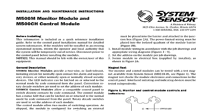
INSTALLATION AND MAINTENANCE INSTRUCTIONS Monitor Module and Control Module SENSOR Division of Pittway 3825 Ohio Avenue St Charles Illinois 60174 FAX 630 377 6495 Installing information is included as a quick reference installation Refer to the control panel installation manual for detailed information If the modules will be installed in an existing system inform the operator and local authority that system will be temporarily out of service Disconnect power to control panel before installing the modules This manual should be left with the owner user of this be placed into the barrier and attached to the junc box Figure 2A The power limited wiring must be into the isolated quadrant of the module barrier 2B Install module wiring in accordance with the job drawings and wiring diagrams Figures 3 9 Set the address on the module per job drawings Secure module to electrical box supplied by installer as in Figure 2A Description Monitor Modules provide a two wire or fault tolerant circuit for normally open contact fire alarm and supervi devices or either normally open or normally closed security The LED indicator can be latched on or returned to the mode by code command from the panel Convenient ro decade switches are used to set the address of each module Control Modules allow a compatible control panel to discrete contacts by code command The control module a status LED that can be latched on or returned to the normal by code command from the panel Rotary decade switches used to set the address of each module control module offers two modes of switching operation As the module is configured for switching an external source to notification appliances The external power can be a DC power supply or an audio amplifier up to Vrms In this mode the module reports supervision status of connected loads to the control panel Load circuit status is re as a NORMAL OPEN or SHORTED circuit Two pairs of termination points are available for fault tolerant wiring second mode of switching operation allows the panel to con one Form C SPDT set of contacts Circuit connections to the are not supervised by the module This mode is enabled breaking two external tabs on the module Requirements insure proper operation these modules shall be connected to compatible system control panels only M500M and M500CH Devices and M500CH modules mount directly to 4 square electri boxes as shown in Figure 2A The box must have a minimum of 21 8 All wiring must conform to applicable local codes ordi and regulations When using control modules in limited applications the System Sensor CB500 Barrier must be used to meet UL requirements the separation of power limited and nonpower lim terminals and wiring The barrier must be inserted a 4 x4 x21 8 junction box and the control module Manuals Online Test monitor and control modules can be tested with a test mag available from System Sensor M02 04 01 see Figure 1 The test checks the module electronics and connections to the panel Interfaced initiating and indicating devices must be independently 1 Monitor and control module controls and LED 5 5 DECADE SWITCHES TEST 2A Module mounting with barrier 2B Monitor Module Wiring Diagrams 3 Typical 2 wire initiating circuit configuration NFPA Style A or B PANEL OR DEVICE NEXT MODULES TO LISTED COMPATIBLE PANELS ONLY NUMBER OF UL LISTED CONTACT CLOSURE MAY BE USED DO NOT MIX FIRE INITIATING SUPERVISORY OR DEVICES ON THE SAME MODULE LINE VDC MAX PAIR RECOMMENDED WIRING SHOWN IS SUPERVISED AND POWER LIMITED 4 Typical fault tolerant initiating circuit configuration NFPA Style D PANEL OR DEVICE MODULES TO LISTED COMPATIBLE CONTROL PANELS ONLY LINE VDC MAX PAIR RECOMMENDED K EOL DEVICE CIRCUIT NFPA STYLE A OR B LIMITED 230 A MAX 12 VDC MAX INSTALLATION WIRING SHALL NOT 40 OHMS OR 2500 FEET 12 18 AWG CONTACT CLOSURE DEVICES PER INSTALLATION INSTRUCTIONS NEXT NUMBER OF UL LISTED CONTACT CLOSURE MAY BE USED DO NOT MIX FIRE INITIATING SUPERVISORY OR DEVICES ON THE SAME MODULE RESISTOR INTERNAL AT 8 9 WIRING SHOWN IS SUPERVISED AND POWER LIMITED DEVICE CIRCUIT NFPA STYLE D LIMITED 230 A MAX 12 VDC MAX INSTALLATION WIRING SHALL NOT 40 OHMS OR 2500 FEET 12 18 AWG CONTACT CLOSURE DEVICES PER INSTALLATION INSTRUCTIONS Control Module Wiring Diagrams 5 Typical indicating circuit configuration NFPA Style W MODULES TO LISTED COMPATIBLE PANELS ONLY PANEL OR DEVICE LINE VDC MAX PAIR RECOMMENDED NEXT WIRING SHOWN IS SUPERVISED AND POWER LIMITED VDC BRANCH CIRCUIT NOT LOOP WIRE ON TERMINALS 4 BREAK WIRE RUN TO PROVIDE OF CONNECTIONS REGULATED 24 VDC SUPPLY LISTED FOR FIRE WITH BATTERY BACKUP LOSS OF PRIMARY POWER POWER SOURCE MUST BE LIMITED PER NFPA 70 9 8 7 6 5 DO NOT TERMINAL 5 APPLIANCE CIRCUIT IAC NFPA STYLE W UL LISTED INDICATING APPLIANCES LOAD 2 A 30 VDC 1 A 30 VDC 6 PF DUTY 6 A 30 VDC 35 PF NEXT CONTROL MODULE OR END LINE RELAY EOLR ONE EOLR PER 24 VDC BRANCH CIRCUIT POLARITIES ARE IN ALARM EOL LISTED EOL RELAY ENERGIZED VDC COIL EQUAL Manuals Online 6 Typical fault tolerant indicating circuit configuration NFPA Style X LINE VDC MAX PAIR RECOMMENDED MODULES TO LISTED COMPATIBLE PANELS ONLY PANEL OR DEVICE VDC BRANCH CIRCUIT NOT LOOP WIRE ON TERMINALS 4 BREAK WIRE RUN TO PROVIDE OF CONNECTIONS REGULATED 24 VDC SUPPLY LISTED FOR FIRE WITH BATTERY BACKUP LOSS OF PRIMARY POWER POWER SOURCE MUST BE LIMITED PER NFPA 70 WIRING SHOWN IS SUPERVISED POWER LIMITED NEXT APPLIANCE CIRCUIT IAC NFPA STYLE X UL LISTED INDICATING APPLIANCES LOAD 1.5 A 30 VDC 1 A 30 VDC 6 PF DUTY 6 A 30 VDC 35 PF 9 8 7 6 5 DO NOT TERMINAL 5 NEXT CONTROL MODULE OR END LINE RELAY EOLR ONE EOLR PER 24 VDC BRANCH CIRCUIT POLARITIES ARE IN ALARM RESISTOR IS AT 8 9 LISTED EOL RELAY ENERGIZED COIL EQUAL 7 Typical wiring for speaker supervision and switching NFPA Style W MUST BE SUPERVISED PER NFPA MODULES TO LISTED COMPATIBLE PANELS ONLY LINE VDC MAX PAIR RECOMMENDED PANEL OR DEVICE NEXT BRANCH CIRCUIT NOT LOOP WIRE AROUND TERMINALS 4 BREAK WIRE TO ENSURE OF CONNECTIONS AMPLIFIER Vrms MAX A 70.7V AUDIO AMPLIFIER IS USED TERMINALS 1 AND 2 ARE POWER LIMITED TERMINALS 3 9 ARE NONPOWER LIMITED IN THIS CASE THE CB500 BARRIER REQUIRED OTHERWISE ALL TERMINAL WIRING IS POWER LIMITED THE CB500 A LABEL INDICATING WHICH TERMINALS ARE NONPOWER LIMITED THIS MUST BE PLACED OVER THE POWER