System Sensor m500dm-installation

File Preview
Click below to download for free
Click below to download for free
File Data
| Name | system-sensor-m500dm-installation-3140869527.pdf |
|---|---|
| Type | |
| Size | 629.26 KB |
| Downloads |
Text Preview
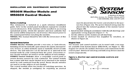
SYSTEM SENSOR Division of Pittway 3825 Ohio Avenue St Charles Illinois 60174 FAX 630 377 6495 AND MAINTENANCE INSTRUCTIONS Dual Monitor Module Operating Voltage Resistance IDC wiring resistance Range to 32 VDC Ohms Ohms to 120 0 to 49 to 93 Noncondensing H x 4 W x 11 4 Electrical Box Installing information is included as a quick reference installation Refer to the control panel installation manual for detailed information If the modules will be installed in an existing system inform the operator and local authority that system will be temporarily out of service Disconnect power to control panel before installing the modules This manual should be left with the owner user of equipment Description Dual Monitor Module is intended for use in intelligent two systems It provides two independent 2 wire initiating device IDC at two separate consecutive addresses It is capable monitoring normally open contact fire alarm and supervisory de or either normally open or normally closed security devices module has a single panel controlled red LED Requirements ensure proper operation these modules shall be connected to compatible system control panels only directly to 4 square electrical boxes see Figure 2A Surface mounted box must have a minimum depth of 21 8 boxes SMB500 are available from System Sensor All wiring must conform to applicable local codes ordi and regulations This module is intended for limited wiring only Install module wiring in accordance with the job drawings and wiring diagrams Set the address on the module per job drawings Monitor module L using terminals 6 and 7 responds the address set on the code switches Monitor module H terminals 8 and 9 will automatically respond at the higher address For example if the code switches are set 76 module L will respond at address 76 and module H respond at address 77 Use caution to avoid duplicate of modules on the system Manuals Online D Mounts to a 4 square by 21 8 deep box Secure module to electrical box supplied by installer as in Figure 2A 1 Controls and indicators 6 7 8 9 0 2A Module mounting 2B 3 Typical 2 wire initiating circuit configuration NFPA Style B INITIATING DEVICE CIRCUITS L H POWER LIMITED TO 230 A 12VDC MAX NEXT K EOL K EOL NUMBER OF UL LISTED CONTACT CLOSURE MAY BE USED DO NOT MIX FIRE INITIATING SUPERVISORY OR DEVICES ON THE SAME MODULE CONTACT CLOSURE DEVICES PER INSTALLATION INSTRUCTIONS 6 7 8 9 LINE VDC MAX PAIR RECOMMENDED A TERMINALS 6 7 RESPONDS AT ADDRESS ON CODE SWITCHES MONITOR B TERMINALS 8 9 AT NEXT HIGHER ADDRESS PANEL OR DEVICE MODULES TO LISTED COMPATIBLE PANELS ONLY WIRING SHOWN IS SUPERVISED AND POWER LIMITED Limited Warranty Sensor warrants its enclosed module to be free from defects in ma and workmanship under normal use and service for a period of years from date of manufacture System Sensor makes no other ex warranty for this module No agent representative dealer or em of the Company has the authority to increase or alter the or limitations of this Warranty The Company obligation of Warranty shall be limited to the repair or replacement of any part of module which is found to be defective in materials or workmanship normal use and service during the three year period commencing the date of manufacture After phoning System Sensor toll free 800 SENSOR2 736 7672 for a Return Authorization number defective units postage prepaid to System Sensor Repair Depart RA 3825 Ohio Avenue St Charles IL 60174 Please a note describing the malfunction and suspected cause of failure Company shall not be obligated to repair or replace units which are to be defective because of damage unreasonable use modifica or alterations occurring after the date of manufacture In no case the Company be liable for any consequential or incidental damages breach of this or any other Warranty expressed or implied whatsoever if the loss or damage is caused by the Company negligence or fault states do not allow the exclusion or limitation of incidental or conse damages so the above limitation or exclusion may not apply to This Warranty gives you specific legal rights and you may also have rights which vary from state to state Statement equipment has been tested and found to comply with the limits for a Class B digital device pursuant to Part 15 of the FCC These limits are designed to provide reasonable protection against harmful interference This equipment generates uses and can radio frequency energy and if not installed and used in accordance with the instruction manual may cause harmful interfer to radio communications Operation is subject to the following two conditions 1 This device may not cause harmful radiation 2 this device must accept any interference received including interference that may cause undesired operation Manuals Online System Sensor 1999